

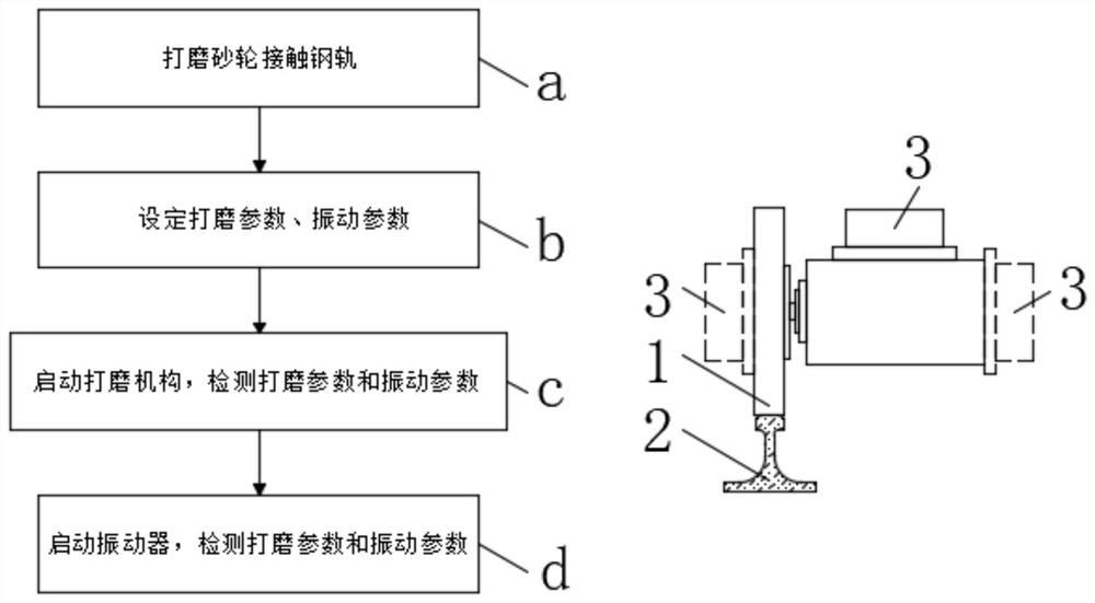
Vibration grinding steel rail grinding method
A technology of vibratory grinding and vibration direction, which is applied in the direction of track, track laying, track maintenance, etc. It can solve the problems of high development cost of grinding equipment, affecting the service life of track, and inconvenient equipment maintenance, so as to improve grinding efficiency and feed Speed, prolonging service life, reducing or avoiding the effects of surface grinding cracks
- Summary
- Abstract
- Description
- Claims
- Application Information
AI Technical Summary
Problems solved by technology
Method used
Image

Examples
Embodiment 1
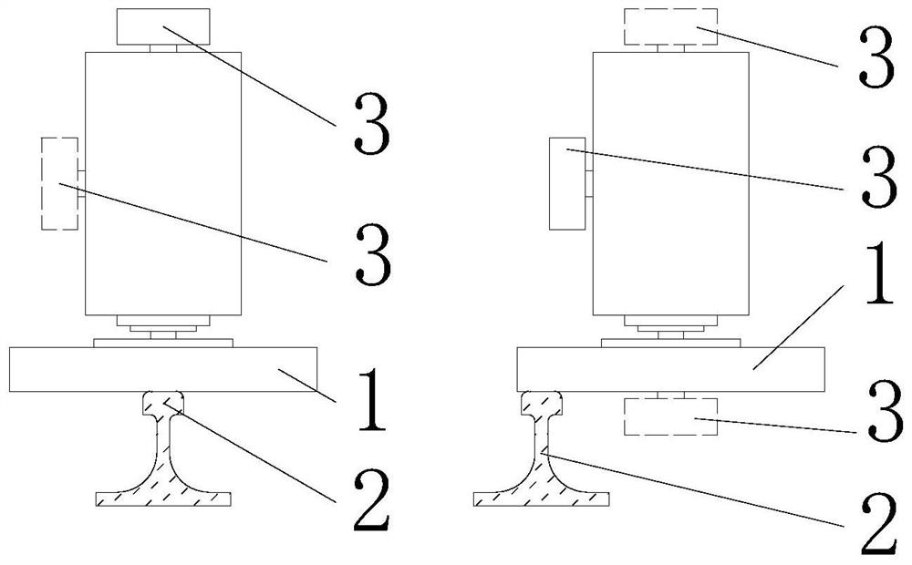
[0047] Embodiment one: if figure 2 and image 3As shown, the high-efficiency vibration grinding rail grinding method of the present invention can be applied to common grinding mechanisms, both for end face grinding and for circumferential grinding. The vibration direction of the grinding wheel 1 can be any direction such as vertical direction, horizontal direction, inclination or a random combination of multiple directions.
Embodiment 2
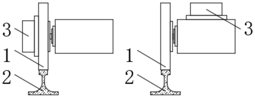
[0048] Embodiment two: if Figure 4 As shown, the high-efficiency vibration grinding rail grinding method of the present invention can be applied to the forming mill of the milling device, the vibration generating device can be placed on the arbitrary position of the grinding wheel 1-the main shaft system, and the vibration direction of the grinding wheel 1 can be vertical direction, horizontal direction, along-line direction, or an unordered combination of directions.
Embodiment 3
[0049] Embodiment three: as Figure 5 As shown, when the high-efficiency vibratory grinding rail grinding method of the present invention is applied to end face grinding, the grinding wheel 1—the axis of the main shaft and the axis of the rail 2 can be at any distance l.
PUM
 Abstract
Description
Claims
Application Information