Construction method of high-altitude large-cantilever concrete beam and slab structure

A technology of concrete beams and construction methods, applied in special structures, formwork/formwork/work frame, formwork/formwork/work frame connectors, etc. Complex, increase the safety risk of high-altitude construction and other issues

Pending Publication Date: 2021-04-13
大连九洲建设集团有限公司
View PDF1 Cites 4 Cited by
  • Summary
  • Abstract
  • Description
  • Claims
  • Application Information

AI Technical Summary

Problems solved by technology

At present, the commonly used large cantilever concrete beam and slab structures mostly adopt the cast-in-place concrete process, such as Chinese patent 200910115141.7, which discloses the construction method of the high-altitude cantilever structure of high-rise buildings. Cast-in-place construction with the load-bearing structure, the structure of the supporting frame is complicated, and a large cantilevered operating platform needs to be erected in a large area at high altitude, which brings many difficulties and inconveniences to the construction; it leads to the extension of the construction period and the addition of the formwork support system At the same time, it also increases the safety risk of high-altitude construction, especially during the process of erecting and dismantling high-altitude operation platforms, construction operators are prone to safety accidents caused by high-altitude falling, causing serious damage to society and families. adverse effects and losses

Method used


Image

  • Construction method of high-altitude large-cantilever concrete beam and slab structure
  • Construction method of high-altitude large-cantilever concrete beam and slab structure
  • Construction method of high-altitude large-cantilever concrete beam and slab structure

Examples


Embodiment Construction

[0033] In order to deepen the understanding of the present invention, the specific implementation of the present invention will be described in detail below in conjunction with the accompanying drawings. This embodiment is only used to explain the present invention and does not constitute a limitation to the protection scope of the present invention.

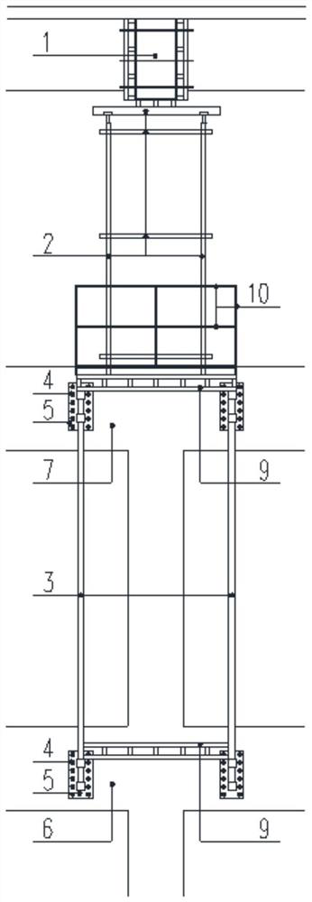
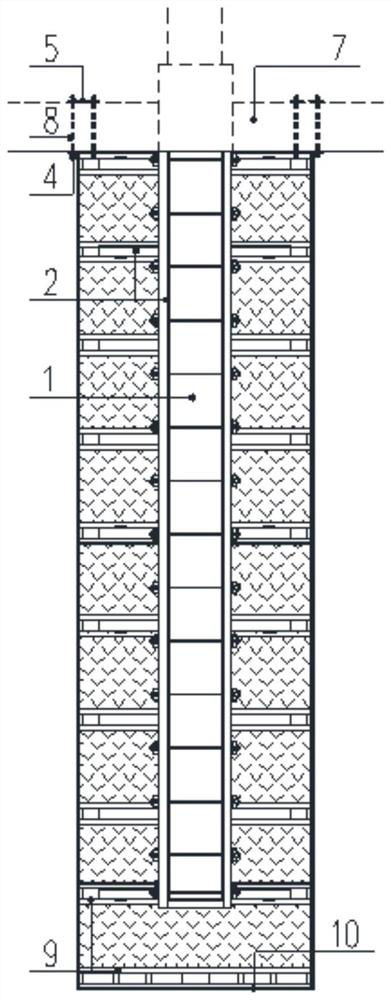
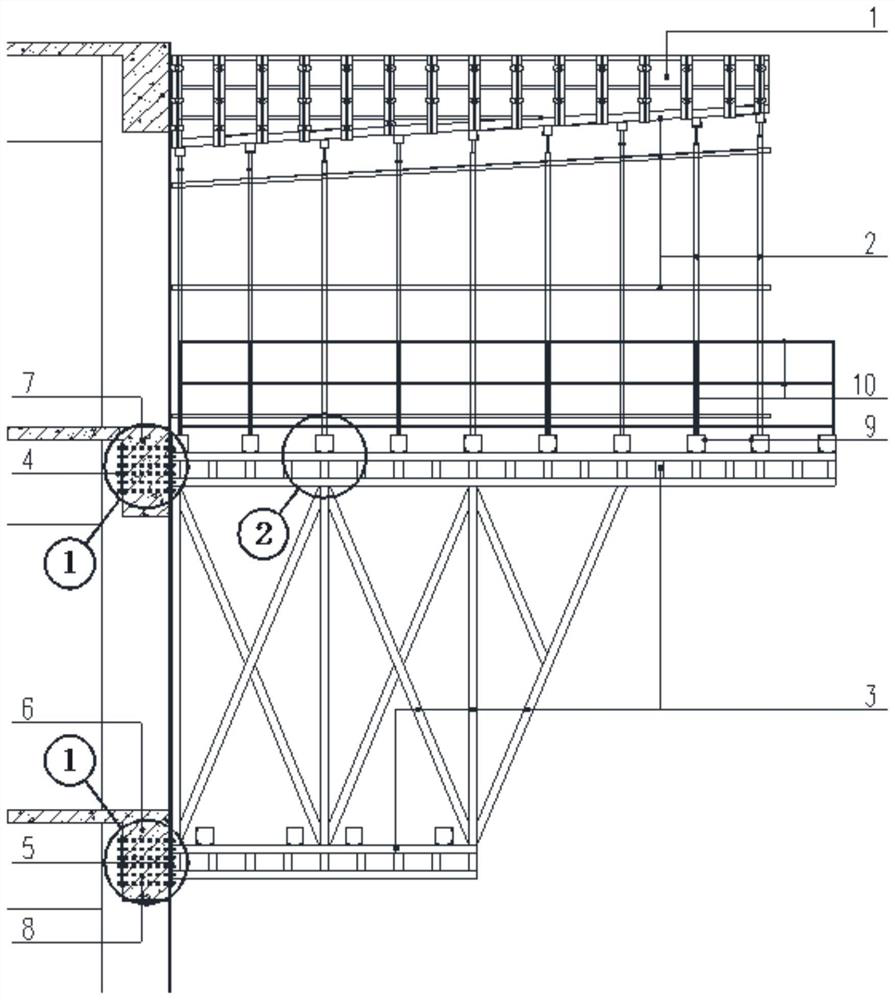
[0034] The structural diagram of the high-altitude large cantilever cast-in-place concrete structure beam formwork support system of the present invention is as follows Figure 1-3 As shown, the structural diagram of the installation of prefabricated concrete composite panels is as follows Figure 4-6 As shown, the structural diagram of the high-altitude large cantilevered concrete beam-slab structure after construction is as follows Figure 7-8 shown.

[0035] from Figure 7-8 It can be seen that the structure diagram of the present invention is composed of two parts: cast-in-situ concrete large cantilever structural beam and...


PUM


Abstract

The invention belongs to the field of building construction, and relates to a construction method of a high-altitude large-cantilever concrete beam and slab structure. The construction method involves a cast-in-place concrete large-cantilever structure beam and an assembled prefabricated concrete composite slab, and the cast-in-place height of the structure beam is reduced through reinforcement optimization; after the beam body concrete strength grade of the cast-in-place concrete large-cantilever structure beam reaches 100% or above of the design strength, a formwork supporting system for the cast-in-place cantilever structure beam is dismounted; the prefabricated concrete assembled composite slab is arranged by means of the cast-in-place concrete large-cantilever structure beam, and no supporting system is arranged on the lower portion of the prefabricated concrete assembled composite slab; and connecting steel bars of the composite slab and the structure beam are assembled, laminated layer concrete is poured, and finally the complete high-altitude large-cantilever concrete beam and slab structure is formed. According to the construction method of the high-altitude large-cantilever concrete beam and slab structure, the construction cost investment for mounting and dismounting a formwork is greatly saved, and the construction method has the advantages of low risk of high-altitude work, simple process, convenient operation, high construction speed, high quality standard, high construction mechanization degree and the like.

Description

technical field [0001] The invention belongs to the field of building construction, and in particular relates to the construction of high-altitude large overhanging concrete beam slabs. Background technique [0002] With the continuous development of the economy, people's requirements for personalization continue to increase. In the field of architecture, individualized and prominent architectural structures are constantly appearing, and the application of various high-altitude and large cantilever structures highlights the uniqueness of the architectural shape. It is currently the most common construction method to set outwardly expanding cantilever spaces on high-rise buildings. By setting personalized cantilever shapes, the requirements of individual buildings can be met. At present, the commonly used large cantilever concrete beam and slab structures mostly adopt the cast-in-place concrete process, such as Chinese patent 200910115141.7, which discloses the construction ...

Claims


Application Information

Patent Timeline
Patent Type & Authority Applications(China)
IPC IPC(8): E04B1/34E04B5/38E04G13/04E04G17/16
CPCE04B1/34E04B5/38E04G13/04E04G17/16
Inventor 李庆新
Owner 大连九洲建设集团有限公司
Why Eureka
Try Eureka