
Preparation method of fly-eye lens with free-form surface substrate

A curved surface compound eye and lens technology, which is applied in the direction of lenses, optics, instruments, etc., can solve the problems of increasing the difficulty and cost of production, and achieve the effects of reducing production cost, simple operation and short processing cycle

Active Publication Date: 2021-04-13
CHANGCHUN INST OF OPTICS FINE MECHANICS & PHYSICS CHINESE ACAD OF SCI
View PDF9 Cites 3 Cited by
  • Summary
  • Abstract
  • Description
  • Claims
  • Application Information

AI Technical Summary

Problems solved by technology

Although the precise measurement and compensation of the geometric error of the CNC machine tool can effectively improve the machining accuracy of the machine tool, it will undoubtedly increase the difficulty and cost of production.

Method used


Image

  • Preparation method of fly-eye lens with free-form surface substrate
  • Preparation method of fly-eye lens with free-form surface substrate
  • Preparation method of fly-eye lens with free-form surface substrate

Examples


Embodiment

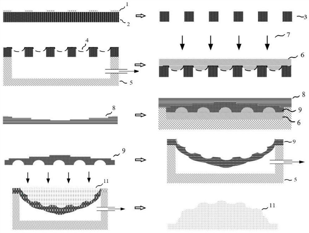
[0030] figure 1 It is a schematic flowchart of a method for preparing a fly-eye lens with a free-form surface substrate according to an embodiment of the present invention.

[0031] Such as figure 1 As shown, the preparation of the fly-eye lens with controllable surface includes the following steps:

[0032] S1: transfer the pattern of the patterned photoresist mask 1 to the substrate of the silicon wafer 2, and carve it into through holes to obtain the microhole array 3 of the silicon wafer 2;

[0033] S2: Cover the prepared PDMS film evenly on the microhole array 3, place it on the plane suction mold 5, and control the negative pressure of the plane suction mold 5 to obtain the The first PDMS concave film 4 in the shape of a sub-eye is required; the air pressure in the air pressure chamber is kept stable, and the second PDMS concave film 9 can be obtained by using the first PDMS concave film 4 to inject glue, cover plate, and unmold.

[0034] The substrate is a silicon wa...


PUM

PropertyMeasurementUnit
thicknessaaaaaaaaaa
Poisson's ratioaaaaaaaaaa

Abstract

The invention provides a preparation method of a fly-eye lens with a free-form surface substrate. The free-form surface fly-eye lens with different gradients of sub-eyes is formed by controlling the film thicknesses of different areas of a film and regularly changing the morphology of the surface. Meanwhile, the imaging effect of each stage of sub-eyes under different object distances is perfected, and the problem that the focal lengths of off-axis light rays are not collinear due to spherical aberration is solved by introducing a free-form surface.

Description

technical field [0001] The invention relates to the technical field of micro-optics and micro-machining, in particular to a method for preparing a fly-eye lens with a free-form surface substrate Background technique [0002] Most of the current curved compound eyes are based on the spherical base. In the traditional spherical base design, non-paraxial rays incident from different angles cannot converge perfectly on the same Gaussian image point after passing through the spherical lens, thus forming spherical aberration. . After these compound eyes on the curved surface are converged, each focal point is located on the Pittsburgh curved surface, which makes it difficult for the fly eye lens to directly match the current planar receiver. In order to solve this problem, by adding multiple lenses or optical waveguides as optical relays, the light from different sub-eyes can be guided to converge on the plane, or the design of non-uniform sub-eyes with multi-focal length can be ...

Claims


Application Information

Patent Timeline
Patent Type & Authority Applications(China)
IPC IPC(8): G02B3/00
CPCG02B3/0031G02B3/0012
Inventor 刘永顺连高歌陶可楷邢燚吴一辉
Owner CHANGCHUN INST OF OPTICS FINE MECHANICS & PHYSICS CHINESE ACAD OF SCI
Learn More