Drainage device in building

A drainage device and construction technology, applied in water supply devices, indoor sanitary plumbing devices, buildings, etc., can solve problems affecting the sleep quality of neighbors, loud noise, pipe blockage, etc., to improve drainage efficiency, reduce noise pollution, The effect of preventing clogging

Pending Publication Date: 2021-04-16
ZHENGZHOU RAILWAY VOCATIONAL & TECH COLLEGE
View PDF8 Cites 0 Cited by
  • Summary
  • Abstract
  • Description
  • Claims
  • Application Information

AI Technical Summary

Problems solved by technology

[0005] At present, building drainage generally uses pipelines for drainage. During the drainage process, pipeline blockages often appear, which brings more troublesome consequences to people's lives; in the prior art, the filtration method is generally used to filter larger impurities. Preventing it from entering the pipeline and causing pipeline blockage has played a certain preventive role, but it cannot fundamentally solve the problem of pipeline blockage; at the same time, when the traditional drainage pipe is draining, the water is directly tilted down by gravity. There will be a lot of noise, which will affect the sleep quality of the neighbors. It needs to be improved, and the noise pollution is small

Method used


Image

  • Drainage device in building
  • Drainage device in building
  • Drainage device in building

Examples


Embodiment 1

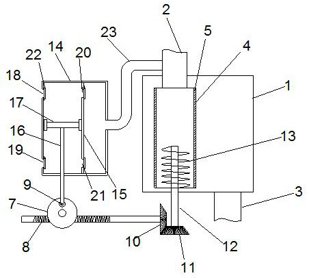
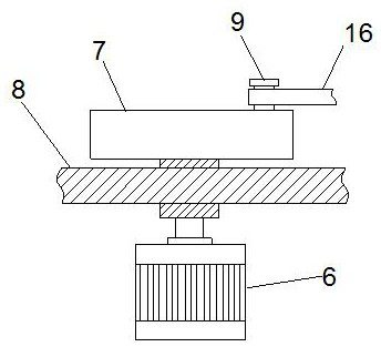
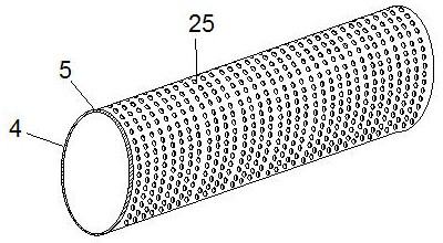
[0039] like Figure 1-5 As shown, a drainage device inside a building includes a casing 1, a downspout 2, and a drainpipe 3; the casing 1 is provided with a rotary drum 4, and the upper end of the rotary drum 4 is connected with a downspout 2, and the rotary The inner side wall of the cylinder 4 is provided with a filter screen 5, and the side wall of the rotating cylinder 4 is provided with a plurality of through holes 25; the casing 1 is in a sealed structure, and the bottom of the casing 1 is connected with the drain pipe 3; The bottom of the cylinder 4 is provided with a rotating shaft 12, the rotating shaft 12 is provided with a helical cutter 13, the other end of the rotating shaft 12 is connected with a second gear 11, the second gear 11 is meshed with the first gear 10, and the first gear 10 is engaged with the second gear 11. A gear 10 is connected with a worm 8, and the worm 8 is matched with a worm wheel 7, which drives the first gear 10 to rotate; the downpipe 2 is...

Embodiment 2

[0042] On the basis of the first embodiment, the air pressure mechanism includes a sealing box 14, and a partition 15 is arranged inside the sealing box 14. One side of the partition 15 is a pressurizing chamber, and the other side of the partition 15 is a The gas collecting chamber; the inside of the pressurizing chamber is provided with a piston plate 17, the piston plate 17 and the inner wall of the pressurizing chamber form an airtight structure through rubber, and the piston plate 17 is slidably connected in the pressurizing chamber; the piston plate 17 One side is connected to the moving rod 16, the moving rod 16 penetrates the sealing box 14, and forms a gap sliding connection with the sealing box 14.

[0043] The other end of the moving rod 16 is connected with a turning block 9, which is arranged on one side of the worm wheel 7, and the turning block 9 and the worm wheel 7 constitute a rotational connection; the turning block 9 is connected to the side wall of the worm...

Embodiment 3

[0046] On the basis of the first embodiment, during the working process of this technical solution, the larger magazines enter the rotating drum 4 with the downpipe 2, and the worm wheel 7 is driven to rotate by the servo motor 6, and the worm wheel 7 drives the worm 8 to rotate; the worm 8 rotates; Drive the first gear 10 and the second gear 11 to rotate, further drive the helical cutter 13 to rotate, and pulverize the larger impurities accumulated in the drum 4; at the same time, the worm gear 7 drives the moving rod 16 and the piston during the rotation process. The plate 17 performs cyclic reciprocating motion in the supercharging chamber. During the upward movement of the piston plate 17, the second intake valve 19 is opened by the action of negative pressure, the gas enters the supercharging chamber from the outside, and the first intake valve 18 is pressurized. The pressure inside the chamber is in a closed state, the first outlet valve 20 is in an open state by the acti...


PUM


Abstract

The invention discloses a drainage device in a building. The drainage device comprises a shell, a downpipe and a drainage pipe, wherein a rotating cylinder is arranged in the shell, the upper end of the rotating cylinder is connected with the downpipe, a filter screen is arranged on the inner side wall of the rotating cylinder, and a plurality of through holes are formed in the side wall of the rotating cylinder; the shell is of a sealed structure, and the bottom of the shell is connected with the drainage pipe; a rotating shaft is arranged at the bottom of the rotating cylinder, a spiral cutter is arranged on the rotating shaft, the other end of the rotating shaft is connected with a second gear, the second gear is connected with a first gear in a meshed mode, the first gear is connected with a worm, and the worm is connected with a worm gear in a matched mode to drive the first gear to rotate; and the downpipe is connected with a pressurizing pipe, the other end of the pressurizing pipe is connected with an air pressure mechanism, and the air pressure mechanism conducts air pressurizing on the downpipe. The sewage discharging effect is further improved, blockage is prevented, the drainage amount is increased, and the use safety is improved.

Description

technical field [0001] The invention belongs to the field of building drainage, in particular to a drainage device inside a building. Background technique [0002] The domestic drainage system is to exclude the sewage from residential buildings, public buildings and factories. The domestic drainage system can be further divided into: a domestic sewage drainage system that excludes flushing toilets and a domestic sewage drainage system that excludes washing wastewater. Domestic wastewater can be treated as miscellaneous water for flushing toilets or landscaping; there is a two-phase flow of water and gas in the drainage pipes inside the building. To prevent toxic and harmful gases from entering the room due to pressure fluctuations, a ventilation system is required. [0003] Chinese Patent Application No. 201921500682.7 discloses an anti-blocking device for a building drain pipe, comprising a water collecting tank, and an upper drain pipe is fixedly connected to the side wal...

Claims


Application Information

Patent Timeline
Patent Type & Authority Applications(China)
IPC IPC(8): E03C1/266E03C1/264E03C1/12
Inventor 李巍
Owner ZHENGZHOU RAILWAY VOCATIONAL & TECH COLLEGE
Why Eureka
Try Eureka