Hydraulic system, construction machine, hydraulic control method, and computer storage medium

A hydraulic system, hydraulic technology, applied in the direction of fluid pressure actuation system components, mechanical equipment, earth movers/shovels, etc., to achieve the effect of suppressing overheating

Pending Publication Date: 2021-04-16
NABLESCO CORP
View PDF1 Cites 0 Cited by
  • Summary
  • Abstract
  • Description
  • Claims
  • Application Information

AI Technical Summary

Problems solved by technology

Therefore, a state may occur where the maximum flow rate of operating oil is not discharged from the hydraulic pump

Method used


Image

  • Hydraulic system, construction machine, hydraulic control method, and computer storage medium
  • Hydraulic system, construction machine, hydraulic control method, and computer storage medium
  • Hydraulic system, construction machine, hydraulic control method, and computer storage medium

Examples


Embodiment Construction

[0035] Next, embodiments of the present invention will be described based on the drawings.

[0036] (construction machinery)

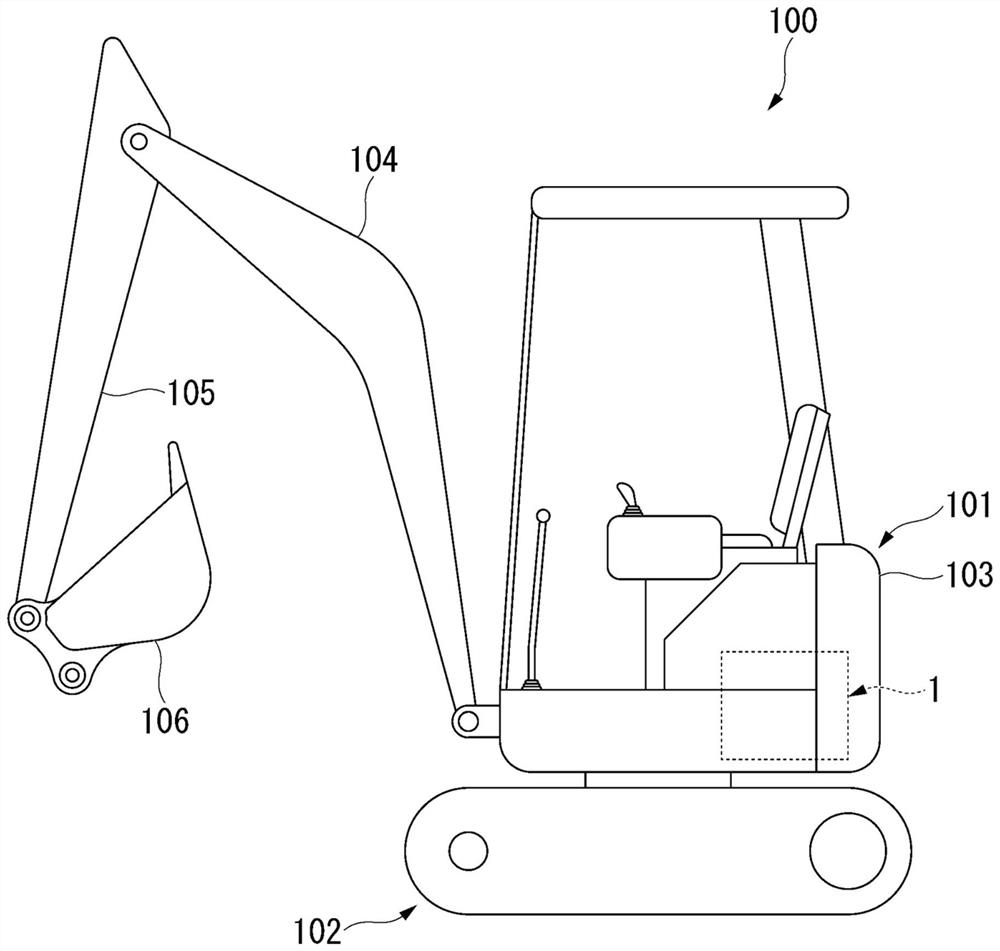
[0037] Such as figure 1 As shown, construction machine 100 is, for example, a hydraulic excavator. The construction machine 100 includes a revolving body 101 and a running body 102 . The revolving body 101 is provided on the running body 102 in a rotatable manner. The hydraulic system 1 is installed on the revolving body 101 .

[0038] The revolving body 101 includes: a cab 103 on which an operator can ride; a boom 104 having one end connected to the cab 103 in a swingable manner; The other end (the end (top) on the side opposite to the cab 103) is connected; The other end (top)) is connected. The hydraulic system 1 is installed in the cab 103 . Cab 103 , boom 104 , arm 105 , and bucket 106 are driven by hydraulic oil supplied from hydraulic system 1 .

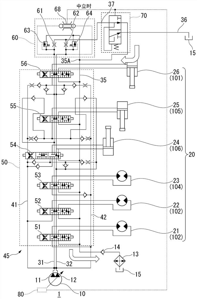
[0039] (Hydraulic system)

[0040] Such as figure 2 As shown, the hydraulic system 1 is...


PUM


Abstract

The invention provides a hydraulic system, a construction machine, a hydraulic control method, and a computer storage medium. The hydraulic system of the present invention returns working oil discharged from an actuator to the tank via an oil cooler. The hydraulic system includes: a throttle; a flow path that connects the throttle and the tank via an oil cooler; a discharge flow path that connects the throttle and the tank; and a switching valve that switches the flow direction of the working oil according to the negative control pressure generated by the throttle. When the negative control pressure generated by the throttle is equal to or higher than the reference, the switching valve causes the hydraulic fluid to flow through the flow path. When the negative control pressure is less than the reference, the switching valve blocks the inflow of hydraulic fluid from the throttle to the flow path, and allows the hydraulic fluid to circulate to the drain flow path.

Description

technical field [0001] The present invention relates to a hydraulic system for controlling the back pressure of a negatively controlled hydraulic system, a construction machine, a hydraulic control method, and a computer storage medium. Background technique [0002] Many machines, such as construction machines, are driven by hydraulic control. Among hydraulic systems that drive construction machines such as hydraulic excavators, there are hydraulic systems using a negative control system. In a hydraulic system using negative control, a pressure relief valve and a throttle that acts as a resistance are provided at the most downstream of a center bypass line of the hydraulic system. The hydraulic system is controlled by feeding back a detection signal based on the control pressure of the throttle to the hydraulic pump, thereby increasing or decreasing the flow rate of the working oil in the center bypass line. [0003] For example, when the operating part is in the neutral p...

Claims


Application Information

Patent Timeline
IPC IPC(8): F15B21/0423F15B11/17F15B13/06F15B21/02E02F9/22
CPCE02F9/2221E02F9/2267E02F9/226E02F9/2282
Inventor 岩崎仁后藤敬介
Owner NABLESCO CORP
Why Eureka
Try Eureka