A kind of clutch nut and its clutch method

A technology of clutch nuts and clutch screws, which is applied in the direction of nuts, bolts, threaded fasteners, etc., can solve the problem of reducing the applicability of sliding screw transmission engineering applications, preventing the axial force of screw transmission from being loaded by nuts and screws, and reducing sliding Solve problems such as screw drive applicability, achieve stable and reliable meshing and separation states, compact size, and simple structure

Active Publication Date: 2021-11-30
WENZHENG COLLEGE OF SOOCHOW UNIV
View PDF0 Cites 0 Cited by
  • Summary
  • Abstract
  • Description
  • Claims
  • Application Information

AI Technical Summary

Problems solved by technology

In order to compensate the axial gap caused by the wear of the screw pair, or to eliminate or reduce the idle stroke during reverse transmission, the nut is often combined or split. In this case, the nut structure is more complicated and needs to be adjusted regularly
[0004] In the sliding screw drive, the nut and the helical surface of the screw are in surface contact, so the bearing capacity is large, and a large axial force can be obtained through a small torque, but in this case, the transmission ratio of the screw drive is usually very small That is to say, the ratio of the rotation angle of the nut relative to the screw to the axial movement of the nut relative to the screw is very large, which reduces the applicability of the sliding screw drive in some engineering applications, such as: the nut needs to move relative to the screw. Situations where a long distance has to be moved to reach the work position
In addition, the current traditional nuts cannot realize the engagement and separation of the screw rod according to the practical engineering requirements, and cannot control the axial force on the screw drive by disengaging the nut from the screw rod, which also reduces some engineering applications of the sliding screw drive. Suitability for the occasion

Method used


Image

  • A kind of clutch nut and its clutch method
  • A kind of clutch nut and its clutch method
  • A kind of clutch nut and its clutch method

Examples


Embodiment 1

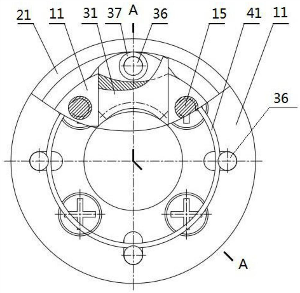
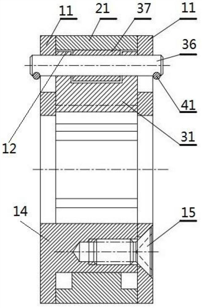
[0045] see Figure 1 to Figure 5 , as shown in the legend therein, a clutchable nut comprising:

[0046] The guide assembly includes two annular end plates 11 respectively sheathed on the radially outer side of the clutched screw at different positions in the axial direction, a rotating guide 12 arranged on at least one annular end plate 11 and at least one annular end plate The radial guide part 13 on the plate 11, and the two annular end plates 11 are relatively fixed;

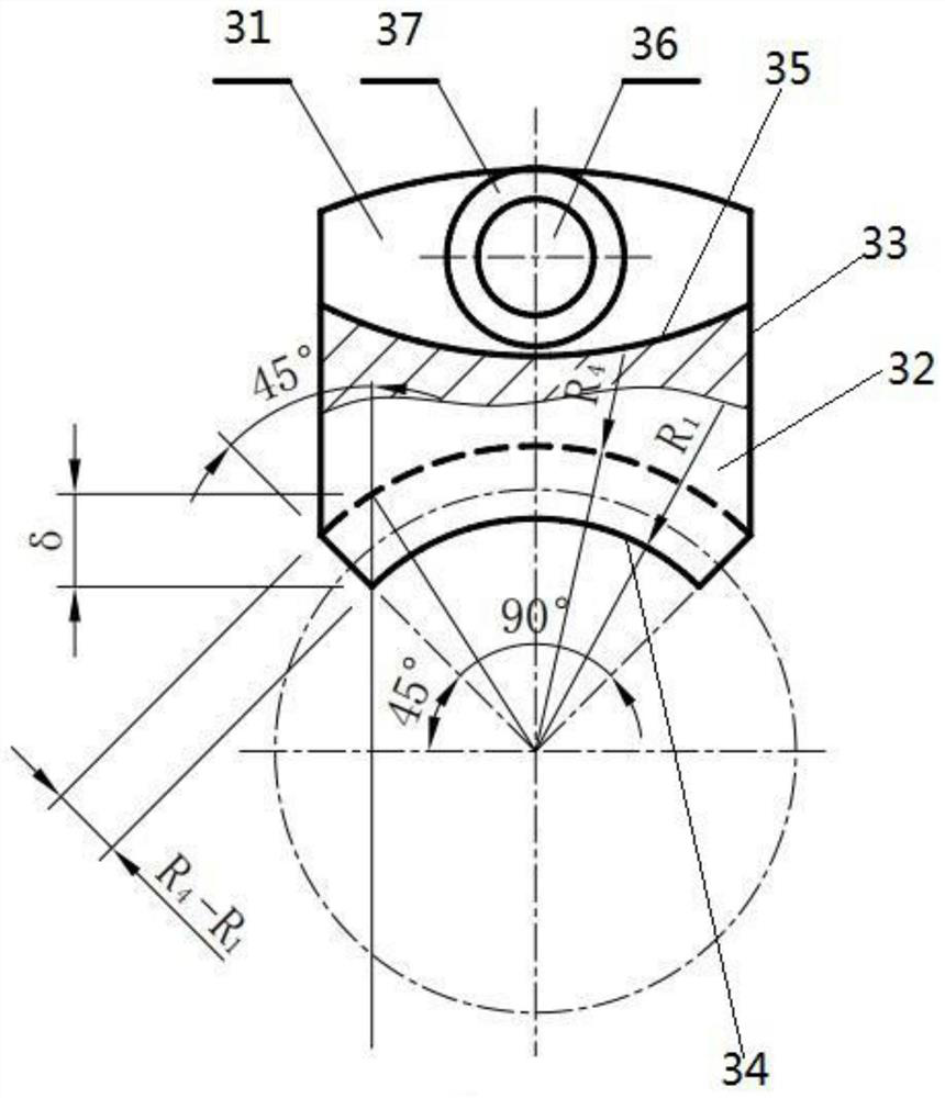
[0047] The steering ring 21 is sheathed on the radially outer side of the clutched screw and is located between two annular end plates 11. The steering ring 21 is rotatably connected to the rotation guide 12 around the central axis of the clutched screw. The steering ring 21 The inner peripheral surface of the inner peripheral surface is provided with a plurality of first concave arc-shaped surfaces 22 uniformly distributed along the circumferential direction and a plurality of second concave arc-shaped sur...


PUM


Abstract

The invention discloses a detachable nut and a detachable method thereof. The detachable nut comprises a guide assembly, a steering ring, a nut assembly and an elastic assembly. The second concave arc surface, the nut assembly includes a plurality of partial nuts, the inner surface of some nuts is provided with a third concave arc surface, and the outer surface of some nuts is provided with a convex arc surface, in the first working state, A plurality of first concave arc-shaped surfaces are respectively rotated to the radially outer sides of the plurality of partial nuts, and the convex arc-shaped surfaces are abutted against the first concave arc-shaped surfaces, and the internal threads of the partial nuts and the external threads of the clutched screw interact with each other. meshing; in the second working state, multiple second concave arc-shaped surfaces are rotated to the radially outer sides of multiple partial nuts respectively, and the external convex arc-shaped surfaces are against the second concave arc-shaped surfaces, and the internal threads of some nuts Separated from the external thread of the clutched screw. The invention has the advantages of simple structure, reliable operation and convenient manufacture, installation and maintenance.

Description

technical field [0001] The invention belongs to the technical field of mechanical transmission, and in particular relates to a clutch nut and a clutch method thereof. Background technique [0002] Screw drive can be divided into sliding screw, rolling screw and static pressure screw according to the friction properties of the screw pair. The present invention relates to sliding screw. Sliding screw drives consist of a screw and a nut and are used to convert rotary motion into linear motion while simultaneously transmitting motion and power. The screw transmission has the advantages of simple structure, convenient manufacture, reliable operation, stable transmission, small and precise linear movement with a large rotation angle, large axial force with a small torque, and self-locking. It is widely used in engineering. Especially in the application of large transmission ratio and high force increase, compared with other transmission schemes, screw transmission has incomparab...

Claims


Application Information

Patent Timeline
Patent Type & Authority Patents(China)
IPC IPC(8): F16B37/08F16B33/02
Inventor 祝佳钱志良
Owner WENZHENG COLLEGE OF SOOCHOW UNIV
Why Eureka
Try Eureka