Valve rod sealing structure and eccentric semi-ball valve

A sealing structure and valve stem technology, which is applied to the valve shell structure, shaft seal, valve details, etc., can solve the problems of valve stem wear, medium particles are isolated between the valve stem and the valve body, and achieve the effect of enhancing the sealing effect

Pending Publication Date: 2021-04-16
SHANDONG AFA FLOW CONTROL
View PDF0 Cites 1 Cited by
  • Summary
  • Abstract
  • Description
  • Claims
  • Application Information

AI Technical Summary

Problems solved by technology

[0005] Therefore, the technical problem to be solved by the present invention is to overcome the technical defect that the valve stem sealing structure in the prior art cannot isolate the medium particles between the valve stem

Method used


Image

  • Valve rod sealing structure and eccentric semi-ball valve
  • Valve rod sealing structure and eccentric semi-ball valve
  • Valve rod sealing structure and eccentric semi-ball valve

Examples


Embodiment 1

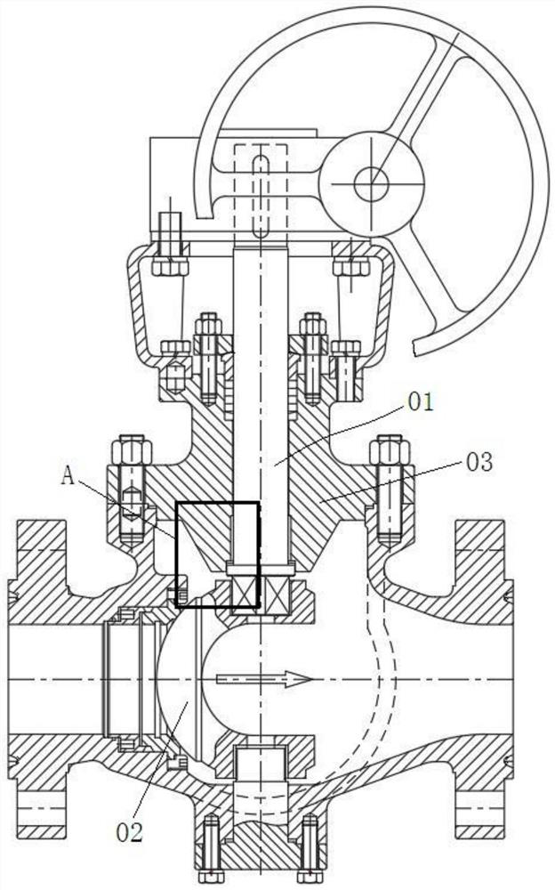
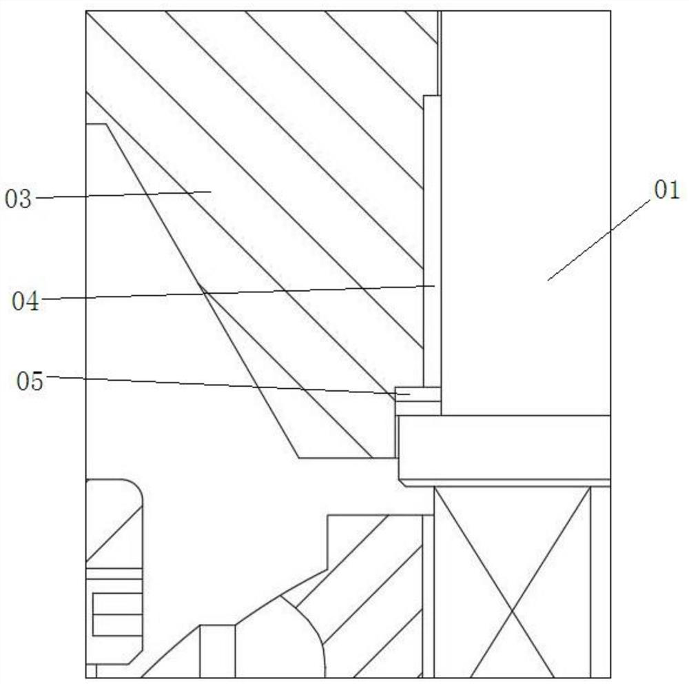
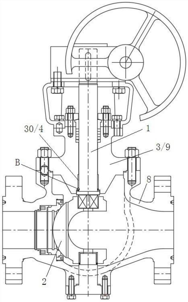
[0038] This embodiment provides a valve stem sealing structure, such as Figure 3-4 As shown, it includes: a lubricating bearing 4, an elastic seal 5, a pressing member 6 and a fixing member 7. The above-mentioned lubricating bearing 4, elastic sealing member 5, pressing member 6 and fixing member 7 are installed on the valve stem 1 close to the valve ball 2 The middle position between a section of one end and the support structure 3 on which the valve stem 1 is installed is used to prevent medium particles from entering between the valve stem 1 and the support structure 3 from this position, thereby preventing the medium particles from affecting the valve stem 1 and the support structure 3 Wear during rotation.

[0039] Specifically, the function of the lubricating bearing 4 is to reduce the rotational friction force, and the elastic sealing member 5 is sleeved on the valve stem 1 with an inverted U-shaped opening facing outward under the action of the fixing member 7 and the...

Embodiment 2

[0050] This embodiment provides an eccentric hemispherical valve, such as Figure 3-4 As shown, it includes: a valve body 8, a valve ball 2 installed inside the valve body 8, a valve stem 1 and a driving device; the valve stem 1 rotatably passes through the valve cover 9 and is fixedly connected to the valve ball 2; the valve ball 2 It is an eccentric hemisphere; it also includes a valve stem sealing structure installed on a section of the valve stem 1 close to the valve ball 2 and the middle part of the valve cover 9 for installing the section of valve stem 1; the valve stem sealing structure is an embodiment Stem seal structure described in 1.

[0051] Due to the adoption of the above-mentioned stem sealing structure, the ball valve of this embodiment naturally has all the advantages brought by the adoption of the above-mentioned structure.


PUM


Abstract

The invention provides a valve rod sealing structure and a ball valve. The valve rod sealing structure comprises a lubricating bearing, an elastic sealing piece, an abutting piece and a fixing piece. The lubricating bearing is used for reducing rotating friction force. The elastic sealing piece is arranged on a valve rod in a sleeving mode with an inverted-U-shaped opening facing outwards under the action of the fixing piece and the abutting piece. The two side walls of the elastic sealing piece are in close contact with the outer wall of the valve rod and the inner wall of a supporting structure correspondingly. After external fluid enters the position from a gap between the valve rod and the supporting structure, the pressure of the fluid presses the middle of the elastic sealing piece, the two side walls of the elastic sealing piece are extruded to be in close contact with the outer wall of the valve rod and the inner wall of the supporting structure correspondingly, and thus the sealing effect is achieved. According to the valve rod sealing structure, most of medium particles can be prevented from entering the position between the valve rod and the supporting structure, thus the valve rod does not rub with the medium particles when rotating, and abrasion is small.

Description

technical field [0001] The invention relates to the technical field of ball valve stem sealing structure, in particular to a sealing structure for the position of a ball valve stem and an eccentric hemispherical valve. Background technique [0002] The eccentric hemispherical valve usually includes a valve body, an eccentric hemispherical body (valve ball) installed inside the valve body, a valve stem, and a driving device, wherein the valve stem is rotatably mounted on the valve body (if it is a top entry ball valve, the valve stem rotatably installed on the valve cover), one end of the valve stem is fixedly connected with the eccentric hemisphere, and the other end is connected with the driving device. The driving device drives the valve stem to rotate, and the valve stem drives the eccentric hemisphere to rotate, thereby switching the rotation state of the eccentric hemisphere to open or close the fluid channel. [0003] The part where the valve stem passes through the v...

Claims


Application Information

Patent Timeline
IPC IPC(8): F16K5/06F16K41/02F16K27/08
Inventor 谢正泽朱志刚吴平叶友海黄亚光陈浩李增有张炎
Owner SHANDONG AFA FLOW CONTROL
Why Eureka
Try Eureka