
A method for implementing non-inductive switching redundant communication based on epa bus

A technology of redundant communication and implementation method, which is applied in the field of digital information transmission, can solve problems such as poor reliability, data discarding, and low efficiency, and achieve high compatibility, increase delay, and ensure real-time performance

Active Publication Date: 2021-06-18
浙江国利信安科技有限公司
View PDF1 Cites 0 Cited by
  • Summary
  • Abstract
  • Description
  • Claims
  • Application Information

AI Technical Summary

Problems solved by technology

Therefore, the application scenario of this solution is too ideal to be applicable to complex network applications; if a ring or star network is used, this solution will not be implemented due to the inconsistency of the order in which packets are received and sent
[0007] 2. The redundancy scheme of this scheme requires the receiving end to receive the data of the two redundant channels in order for judgment. If the order of the data received by the receiving end is different from that of the sending end, the redundancy filtering method in this method will lead to a wrong sequence. This piece of data is discarded. At the same time, if a code error is caused by a system error, the timestamp Cmax of the receiving end is updated incorrectly and is directly updated to a larger value. discarded, poor reliability
[0008] 3. All data is cached in the same queue and judged one by one, which is inefficient. If there are many redundant channels, the efficiency of redundant filtering will be significantly reduced

Method used


Image

  • A method for implementing non-inductive switching redundant communication based on epa bus
  • A method for implementing non-inductive switching redundant communication based on epa bus
  • A method for implementing non-inductive switching redundant communication based on epa bus

Examples


Embodiment Construction

[0034] The present invention will be described in further detail below in conjunction with the accompanying drawings.

[0035] The most notable feature of the EPA bus is that all nodes in the EPA network are under the same clock reference, and the time for all nodes to send messages is a relatively definite time, and the sending interval is the macrocycle time of the EPA network.

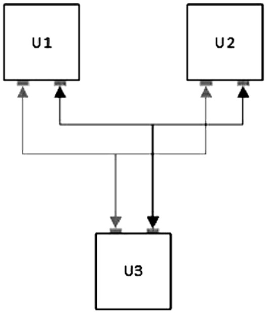
[0036] The entire system of this solution is implemented based on FPGA hardware, which has no additional requirements on the physical layer medium and no restrictions on the topology of the network. The network can be connected end-to-end through communication terminals to form a ring type, or form a bus type, or form a star topology through switches.

[0037] An EPA bus-based non-inductive switching redundant communication implementation method configures the EPA network into a redundant communication network system. The redundant communication network system is not limited by topology, and may be...


PUM


Abstract

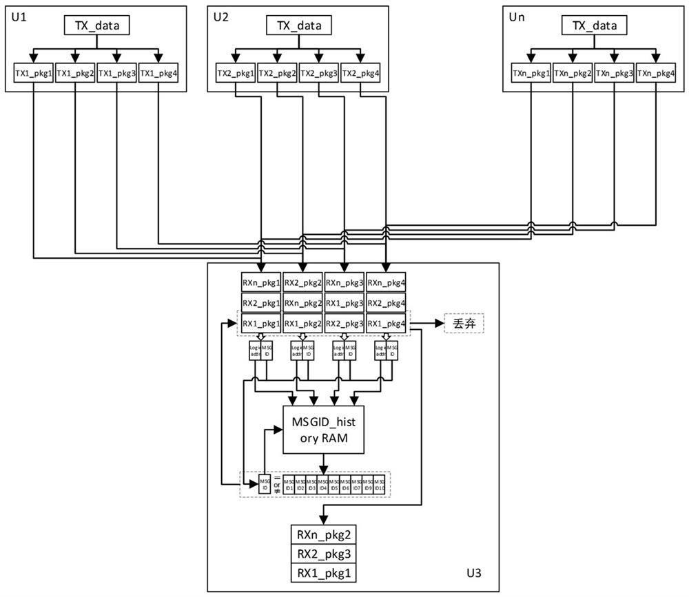
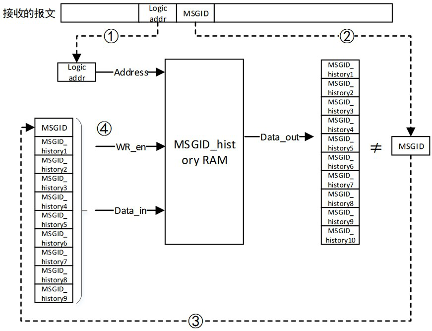
A method for implementing non-inductive switching redundant communication based on an EPA bus, belonging to the technical field of digital information transmission, comprising the following steps: Step 1: a sending end sends a message with exactly the same content to each communication channel; Step 2: each message The communication channel sends its messages from each sending end to each receiving end; Step 3: The receiving end parses out the logical address and message sequence number carried by the front-end message, and reads the data in the history storage area one by one. A historical serial number group composed of historical serial numbers corresponding to the logical address; Step 4: Compare the serial number of the message carried in the currently processed message with the read historical serial number. In this solution, the switching time of different redundant channels is 0, and the system will not cause abnormal packet loss due to channel switching, thereby realizing multi-channel hot redundancy. At the same time, based on the process of data parallel processing, it does not increase additional processing time while realizing multi-channel redundancy, thereby ensuring the real-time performance of EPA communication.

Description

technical field [0001] The invention belongs to the technical field of digital information transmission, and in particular relates to a method for realizing non-inductive switching redundant communication based on EPA bus. Background technique [0002] The EPA (Ethernet for Plant Automation) bus is a real-time Ethernet bus based on the Ethernet physical layer. It is widely used in production, manufacturing and other control fields. Its main communication feature is to use the physical layer of Ethernet as the transmission basis and realize it through the EPA protocol. High real-time reliability transmission provides communication support for the normal operation of the system. [0003] Traditional EPA communication messages do not have the capability of line redundant communication, but the reliability requirements for EPA bus systems are increasingly strong, and ordinary single-channel networks cannot meet the reliability requirements. [0004] The traditional redundancy s...

Claims


Application Information

Patent Timeline
Patent Type & Authority Patents(China)
IPC IPC(8): H04L1/22
CPCY02P90/02
Inventor 王迎陈建飞张驰王海帆
Owner 浙江国利信安科技有限公司
Learn More