Electric appliance fire detector

A technology of fire detectors and electrical appliances, applied in the field of monitoring detectors, can solve problems such as easy to absorb dust monitoring, untimely fire, etc., to reduce the threat of life and property, and reduce the effect of reducing detection sensitivity

Active Publication Date: 2021-04-16
HUNAN SMART QUICK SMART ELECTRONIC TECH CO LTD
View PDF11 Cites 2 Cited by
  • Summary
  • Abstract
  • Description
  • Claims
  • Application Information

AI Technical Summary

Problems solved by technology

[0004] The object of the present invention is to provide an electrical fire detector, which solves the problem that the traditional electrical fire detector is easy to absorb dust and monitors the fire untimely

Method used


Image

  • Electric appliance fire detector
  • Electric appliance fire detector
  • Electric appliance fire detector

Examples


Embodiment 1

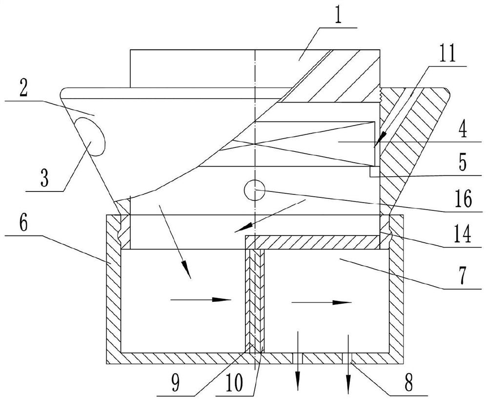
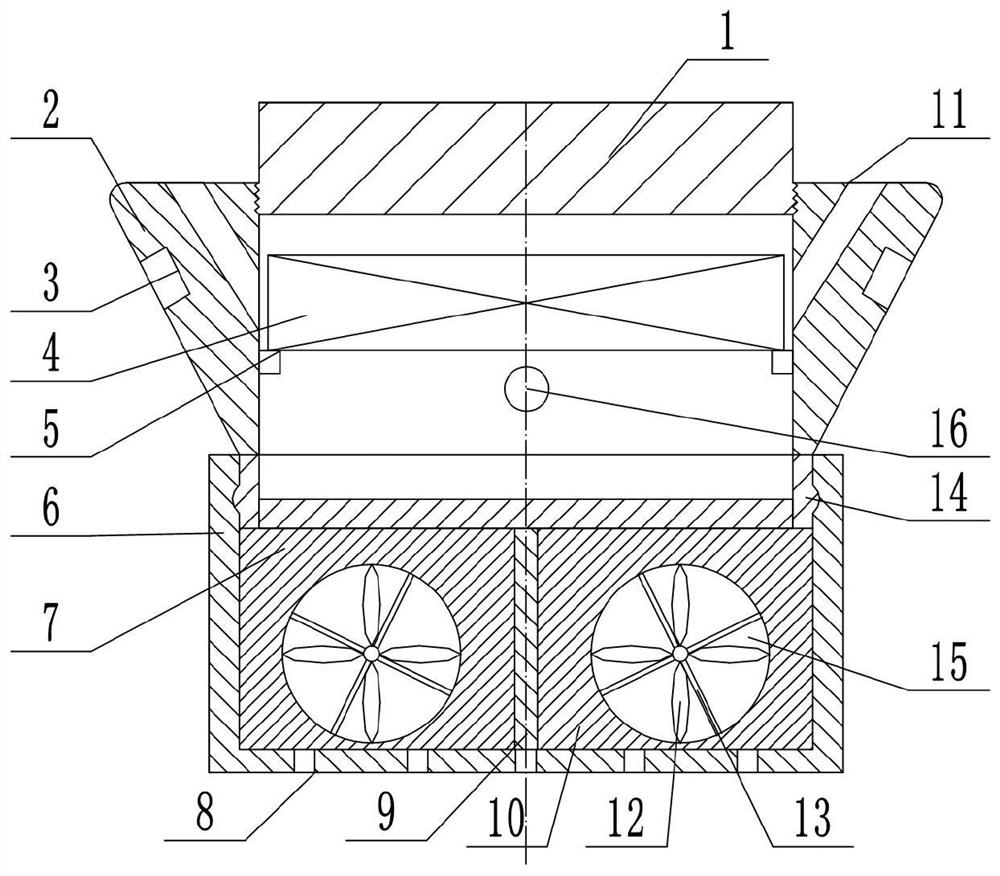
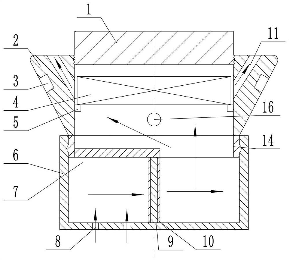
[0037] An electrical fire detector includes an installation support block 1, a housing 2, an alarm device 4 and a smoke sensor probe 16 all arranged in the housing 2, the outer wall of the lower end of the installation support block 1 is provided with external threads, and the housing A cylindrical cavity is coaxially arranged inside the body 2. The housing 2 is a round platform, and its large end is coaxially threaded with the lower end of the installation support block 1 through the internal thread at the upper end of the cavity, and its small end is coaxially threaded with the lower end of the mounting support block 1. The shaft is fixedly connected with a connecting cylinder 14, and an alarm device 4 is installed on the upper part of the cavity. A cylinder 6, the cylinder 6 is rotatably mounted on the connecting cylinder 14, and a fan assembly is fixedly arranged inside the cylinder 6;

[0038] The upper end of the housing 2 is provided with a plurality of ventilation hole...

Embodiment 2

[0050] On the basis of Embodiment 1, an installation snap ring 5 for placing the alarm device 4 is fixedly arranged on the inner wall of the middle part of the cavity.

[0051] The installation snap ring 5 is arranged on the inner wall of the cavity, which is convenient for placing the alarm device 4 .

Embodiment 3

[0053] Further, an annular protrusion is provided on the outer peripheral surface of the connecting cylinder 14, and the cylindrical body 6 is rotatably matched with the annular protrusion of the connecting cylinder 14 through an annular groove on its inner wall, so that the cylindrical body 6 is rotatably mounted on the on the connecting cylinder 14.

[0054] Through the arrangement of the annular protrusion and the annular groove, the rotating connection structure between the cylinder body 6 and the connecting cylinder 14 is more specific, which is convenient for those skilled in the art to implement.


PUM


Abstract

The invention discloses an electric appliance fire detector, which belongs to the technical field of monitoring detectors and comprises a mounting support block, a shell, an alarm device and a smoke sensor probe, the alarm device and the smoke sensor probe are arranged in the shell, an external thread is arranged on the outer side wall of the lower end of the mounting support block, a cylindrical cavity is coaxially arranged in the shell, the shell is a circular truncated cone, the large end of the shell is coaxially in threaded connection with the lower end of the installation supporting block through internal threads at the upper end of the cavity, the small end of the shell is coaxially and fixedly connected with a connecting cylinder, an alarm device is installed on the upper portion of the cavity, the smoke sensor probe is located on the lower portion of the cavity of the shell, an annular protrusion is arranged on the outer circumferential face of the connecting cylinder, a cylinder body with a closed lower end is coaxially arranged outside the connecting cylinder in a sleeving manner, the cylinder body is rotatably mounted on the connecting cylinder, and a fan assembly is fixedly arranged in the cylinder body. According to the electric appliance fire detector, the problems that a traditional electric appliance fire detector is prone to dust adsorption, and a fire cannot be monitored in time are solved.

Description

technical field [0001] The invention belongs to the technical field of monitoring detectors, in particular to electrical fire detectors. Background technique [0002] With the continuous progress of the society, there are more and more types of electronic products. Due to the continuous increase of household appliances, the load on the power cord also increases, which makes the original power cord work overloaded. Many household appliance fires are Caused by violating safety operating procedures. Extinguish the electrical appliances just when they catch fire, which can effectively prevent more serious consequences, so electrical fire detectors are very important for the electrical appliances used in the family to prevent fires. [0003] Existing electrical fire detectors are installed on the top of the room, and exposure to the air for a long time will cause dust inside the device, and the existence of dust will shorten the service life of the device, and at the same time c...

Claims


Application Information

Patent Timeline
Patent Type & Authority Applications(China)
IPC IPC(8): G08B17/10G08B17/12G08B25/00B08B5/02B08B13/00B01D46/10H05F3/00H05K9/00
Inventor 江世军李修连
Owner HUNAN SMART QUICK SMART ELECTRONIC TECH CO LTD
Why Eureka
Try Eureka