Eureka AIR delivers breakthrough ideas for toughest innovation challenges, trusted by R&D personnel around the world.

Silicon steel sheet iron core production line

A silicon steel sheet and production line technology, applied in the manufacture of inductors/transformers/magnets, electrical components, circuits, etc., can solve the problems of reducing production efficiency, limiting lamination speed, and long iron core production cycle, so as to improve the degree of equipment automation, The effect of increasing the lamination speed and shortening the conveying stroke

Pending Publication Date: 2021-04-16
CANWIN AUTOMATIC EQUIP CO LTD
View PDF0 Cites 2 Cited by
  • Summary
  • Abstract
  • Description
  • Claims
  • Application Information

AI Technical Summary

Problems solved by technology

Due to the huge number of laminations and the very high requirements for lamination accuracy, the increase in lamination speed is greatly limited, resulting in a long production cycle of the iron core, huge power consumption, and the failure of the entire iron core due to the drop of the silicon steel sheet due to power failure. phenomenon, which further reduces the generation efficiency
[0004] In addition, the structure of the iron core is various, such as single-phase three-column, single-phase four-column, three-phase three-column, three-phase five-column, etc. Silicon steel coils need to be cut horizontally and vertically, and multi-directional stacking is required , which further increases the difficulty of core stacking and limits the improvement of lamination speed
[0005] At present, most of the silicon steel sheet core production lines on the market need to be completed by manual or semi-automatic production lines. The lamination speed limits the shearing speed, resulting in low production efficiency of the entire production line, which cannot meet the growing market demand.

Method used


Image

  • Silicon steel sheet iron core production line
  • Silicon steel sheet iron core production line
  • Silicon steel sheet iron core production line

Examples


Embodiment Construction

[0030] Embodiments of the present invention are described in detail below, examples of which are shown in the drawings, wherein the same or similar reference numerals designate the same or similar elements or elements having the same or similar functions throughout. The embodiments described below by referring to the figures are exemplary only for explaining the present invention and should not be construed as limiting the present invention.

[0031] In the description of the present invention, several means one or more, and multiple means two or more. Greater than, less than, exceeding, etc. are understood as not including the original number, and above, below, within, etc. are understood as including the original number. If the description of the first and second is only for the purpose of distinguishing the technical features, it cannot be understood as indicating or implying the relative importance or implicitly indicating the number of the indicated technical features or i...


PUM

PropertyMeasurementUnit
thicknessaaaaaaaaaa

Abstract

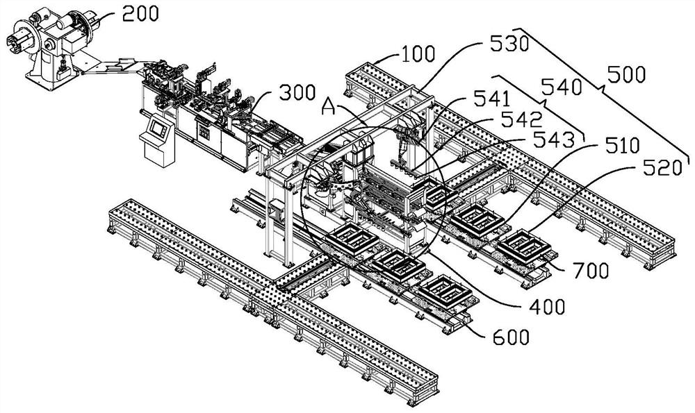
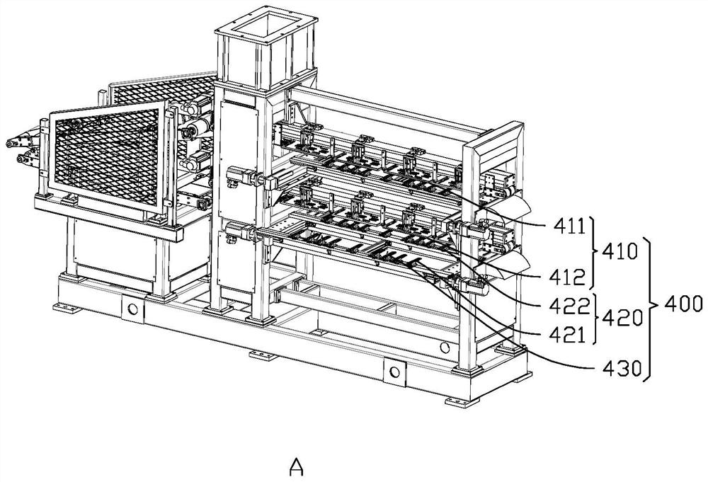
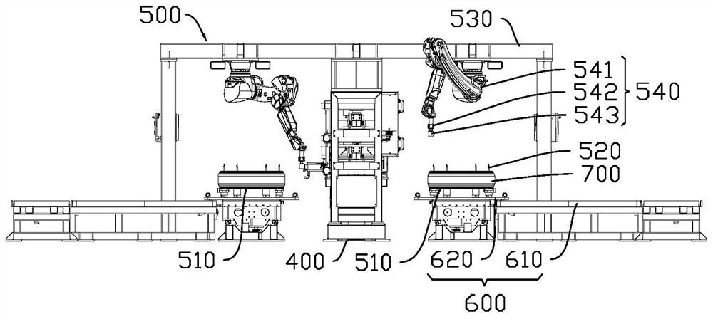
The invention discloses a silicon steel sheet iron core production line comprising an unwinding mechanism, a shearing mechanism, a feeding mechanism, a laminating mechanism and a discharging mechanism; the feeding mechanism comprises a magnetic conveying belt, a feeding piece and a first positioning rod; the magnetic conveying belt comprises an upper conveying belt body and a lower conveying belt body, and the feeding piece can extend out in parallel in the orthogonal direction of the magnetic conveying belt; a first feeding sub-table and a second feeding sub-table are mounted below the upper conveying belt and move oppositely; a third feeding sub-table and a fourth feeding sub-table are mounted below the lower conveying belt and move oppositely; the first positioning rod is used for positioning silicon steel sheets, and the lamination mechanism comprises a lamination table, a cantilever beam and two six-degree-of-freedom manipulators; the six-degree-of-freedom mechanical arm is hoisted on the cantilever beam and comprises an electric permanent magnet used for attracting the silicon steel sheets; and the discharging mechanism comprises a sliding plate, and the stacking table is placed on a sliding plate. According to the silicon steel sheet iron core production line, the equipment automation degree can be improved, the lamination speed is increased, and thus the production efficiency of the production line is improved.

Description

technical field [0001] The invention relates to the field of transformer iron core production equipment, in particular to a silicon steel sheet iron core production line. Background technique [0002] With the development of science and technology, people's dependence on electricity continues to increase, and the demand for electricity continues to increase. As the key equipment in the power transmission work, the market demand of the transformer is also increasing. The iron core is the most critical part of the transformer, and the quality of the iron core plays a decisive role in the performance of the transformer. [0003] Most of the existing iron cores are made by stacking a certain number of silicon steel sheets, and the stacking of silicon steel sheets is a very high-end manufacturing process. The silicon steel sheet is generally only 0.27 mm thick. An ordinary ultra-high voltage transformer generally needs to stack more than 32,000 silicon steel sheets, and the pos...

Claims


Application Information

Patent Timeline
Patent Type & Authority Applications(China)
IPC IPC(8): H01F41/02
Inventor 黄超明
Owner CANWIN AUTOMATIC EQUIP CO LTD
Why Eureka
Eureka Blog
Learn More