Construction method of prefabricated assembly and cast-in-place concrete topping for irrigation channels

A prefabricated assembly and construction method technology, which is applied to irrigation pipelines, artificial waterways, water conservancy projects, etc., can solve the problems of weak connection strength between the roof and the channel, weak connection strength, and easy falling off of the roof, so as to enhance the ability of digging and cutting soil, Effect of reducing friction and reducing construction workload

Active Publication Date: 2022-02-25
ZHEJIANG UNIV CITY COLLEGE
View PDF5 Cites 0 Cited by
  • Summary
  • Abstract
  • Description
  • Claims
  • Application Information

AI Technical Summary

Problems solved by technology

The existing concrete prefabrication and assembly technology for irrigation channels has problems such as poor connection and joint water penetration. The existing concrete capping includes cast-in-place concrete capping and prefabricated concrete capping, and there are problems such as weak connection between the capping and the channel.
[0003] Therefore, it is necessary to design a new construction method of prefabricated assembly and cast-in-place concrete roofing for irrigation canals, which can effectively reduce engineering costs, adopt centralized prefabrication and on-site assembly methods for construction, and speed up construction. The cast-in-place concrete roofing formwork system effectively solves the traditional The connection strength between the concrete cap and the concrete channel is weak, and the cap is easy to fall off

Method used


Image

  • Construction method of prefabricated assembly and cast-in-place concrete topping for irrigation channels
  • Construction method of prefabricated assembly and cast-in-place concrete topping for irrigation channels
  • Construction method of prefabricated assembly and cast-in-place concrete topping for irrigation channels

Examples


Embodiment Construction

[0043]The present invention will be further described below in conjunction with the examples. The description of the following examples is provided only to aid the understanding of the present invention. It should be pointed out that for those skilled in the art, without departing from the principle of the present invention, some improvements and modifications can be made to the present invention, and these improvements and modifications also fall within the protection scope of the claims of the present invention.

[0044] As an embodiment, the present invention provides a construction method for prefabricated assembly of irrigation canals and topping with cast-in-place concrete, comprising the following steps,

[0045] 1) Rapid excavation of U-shaped grooves:

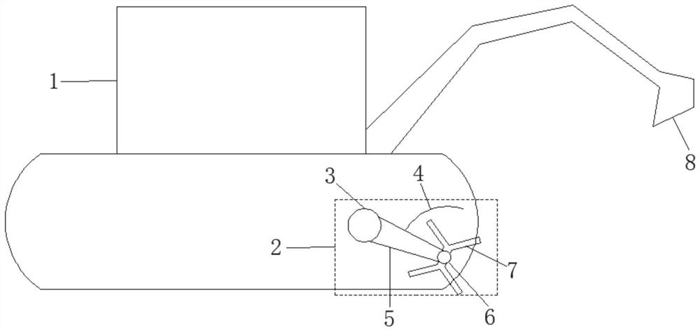
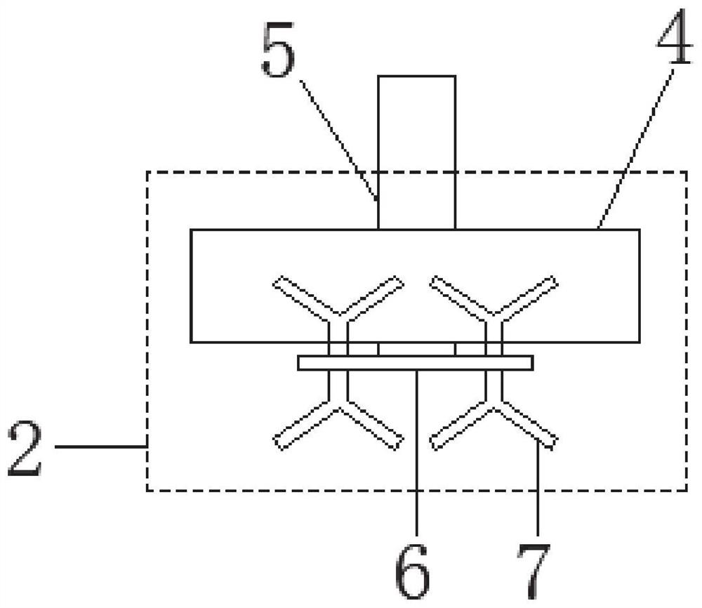
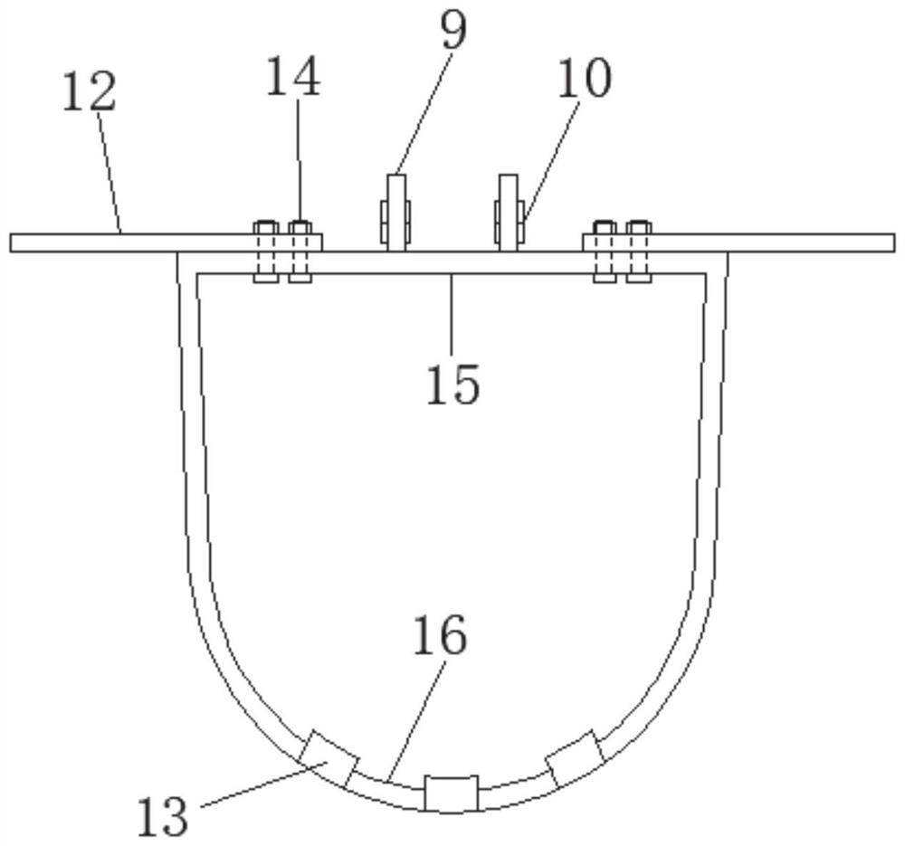
[0046] like Figure 1-4 As shown, at the design position, the excavator 1 is used for excavation. When excavating, first use the soil loosening device 2 provided at the front end of the chassis of the excavator 1 to...


PUM


Abstract

The invention relates to a construction method for prefabricated assembly and cast-in-situ concrete topping of irrigation canals, comprising steps: step 1, use an excavator to excavate at the design position, when excavating, first use the loose soil arranged at the front end of the excavator chassis The device loosens the pre-excavated trench soil, and then cooperates with the U-shaped bucket to easily excavate the U-shaped trench foundation pit; step 2, after the bottom of the U-shaped trench is compacted, the cushion layer is laid, and the cushion layer is laid between the soil bodies with concrete. The upper part of the layer is sprayed with polytetrafluoroethylene coating. The beneficial effects of the present invention are: the groove can be formed at one time under the construction conditions of hard soil and frozen soil, the slope surface is smooth and flat, the slope top is straight and beautiful, and no manual trimming is required; the prefabricated U-shaped groove can be produced in an assembly line, and the production efficiency Higher; reduces the workload of on-site construction; reduces the demand for hoisting accuracy and reduces the difficulty of construction; solves the problems of water permeation in the connection gap of prefabricated U-shaped grooves, weak connection strength of traditional concrete topping and concrete channels, and easy falling off of topping.

Description

technical field [0001] The invention relates to an artificial waterway structure for agricultural soil irrigation and / or drainage, in particular to a construction method for prefabricated assembly of irrigation channels and topping with cast-in-place concrete. Background technique [0002] Concrete irrigation channels are widely used in farmland water conservancy projects. How to quickly realize the prefabricated assembly of concrete irrigation channels and ensure the quality of cast-in-place concrete capping is very important. The existing concrete prefabrication and assembly technology for irrigation channels has problems such as poor connection and joint water permeability. The existing concrete capping includes cast-in-place concrete capping and prefabricated concrete capping, and there are problems such as weak connection between the capping and the channel. [0003] Therefore, it is necessary to design a new construction method of prefabricated assembly and cast-in-pla...

Claims


Application Information

Patent Timeline
Patent Type & Authority Patents(China)
IPC IPC(8): E02B13/00E02F5/08E02F5/02E02B5/02
Inventor 刁红国侯梦颖王新泉魏纲崔允亮阙逸琛
Owner ZHEJIANG UNIV CITY COLLEGE
Why Eureka
Try Eureka