Construction method of cast-in-place drainage ditch

A construction method and drainage ditch technology, which can be applied to side ditches/curbs, roads, buildings, etc., can solve the problems of insufficient excavation capacity of special-shaped bucket excavators, concrete that is easy to leak vibration, and cumbersome problems, and achieve enhanced excavation Soil cutting ability, smooth and flat slope, and the effect of improving the quality of finished products

Active Publication Date: 2021-01-15
齐河恒晟公路工程有限责任公司
View PDF5 Cites 0 Cited by
  • Summary
  • Abstract
  • Description
  • Claims
  • Application Information

AI Technical Summary

Problems solved by technology

At present, the drainage ditch construction usually uses manual and mechanical excavation of the trench, and manual repair of the trench, which is prone to over-excavation and under-excavation, which is time-consuming and labor-intensive.
The traditional formwork and slipform construction procedures of drainage ditches are cumbersome, the pouring efficiency is low, and vibration leakage is easy to cause concrete quality problems during vibration
Even though some new drainage ditch construction equipment has appeared and solved some problems, there are still insufficient cutting and digging capabilities of special-shaped bucket excavators in trenches, and the construction of drainage ditch pouring equipment still requires a lot of manual assistance, and the equipment is heavy and can Problems such as high consumption and low cost performance

Method used


Image

  • Construction method of cast-in-place drainage ditch
  • Construction method of cast-in-place drainage ditch
  • Construction method of cast-in-place drainage ditch

Examples


Embodiment Construction

[0038] The present invention will be further described below in conjunction with the examples. The description of the following examples is provided only to aid the understanding of the present invention. It should be pointed out that for those skilled in the art, without departing from the principle of the present invention, some improvements and modifications can be made to the present invention, and these improvements and modifications also fall within the protection scope of the claims of the present invention.

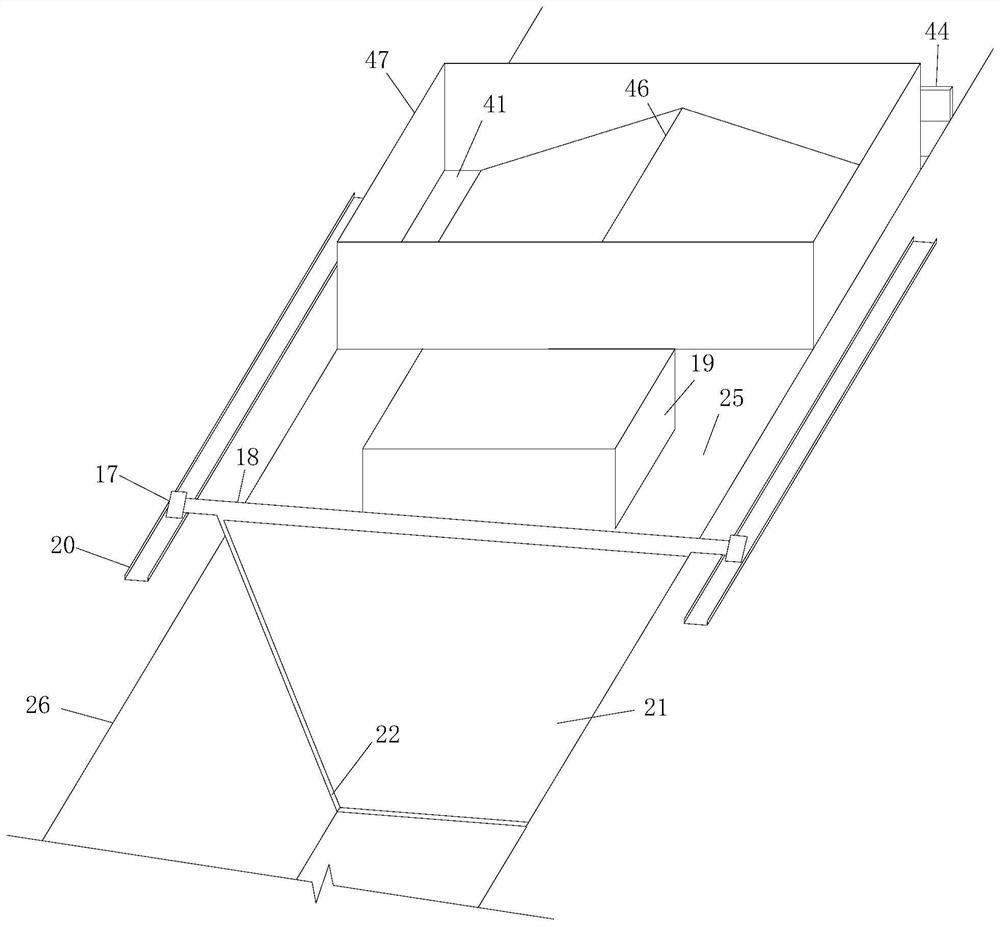
[0039] The construction method of the cast-in-place drainage ditch, according to the engineering design requirements, the drainage ditch construction equipment can cast-in-situ rectangular drainage ditch and trapezoidal drainage ditch, this patent only takes the construction method of the cast-in-situ trapezoidal drainage ditch as an example, including the following steps:

[0040] Step 1. According to the design size of the drainage ditch, select and assemble the e...


PUM


Abstract

The invention relates to a construction method of a pour-in-place drainage ditch. The construction method comprises the following steps of 1, selecting and assembling drainage ditch soil digging and cutting construction equipment; 2, digging a groove foundation pit by using a digging machine with a soil loosening device and a special-shaped digging bucket; 3, finishing a groove by using a drainageditch pouring construction equipment travelling system, arranging a drainage ditch sliding mold below an operation platform, and arranging a pouring funnel with a hydraulic system at the position, corresponding to a steel mold, above the operation platform; 4, pouring concrete; 5, vibrating the concrete; 6, striking off and plastering the drainage ditch by using a striking-off and collecting device; and 7, arranging an expansion joint and curing the concrete. The method has the beneficial effects that a soil loosening device of the drainage ditch soil digging and cutting construction equipment can be used for turning and loosening a pre-digging groove soil layer, the groove foundation pit can be easily dug with the cooperation of the special-shaped digging bucket, so that the soil diggingand cutting capability is enhanced, the groove can still be formed at one time under the construction condition of the hard soil and the frozen soil, the slope surface is smooth and flat, the slope top is straight and attractive, and manual finishing is not needed.

Description

technical field [0001] The invention relates to a cast-in-place drainage ditch, in particular to a construction method for a cast-in-situ drainage ditch. Background technique [0002] With the rapid development of our country and the increasingly developed road traffic network, the subgrade drainage system plays a key role in the normal use of traffic roads. Construction of subgrade drainage ditches is an indispensable link in road construction. At present, drainage ditch construction usually uses manual and mechanical excavation of the trench, and manual repair of the trench, which is prone to over-excavation and under-excavation, which is time-consuming and labor-intensive. The traditional formwork and slipform construction procedures of drainage ditches are cumbersome, the pouring efficiency is low, and vibration leakage is easy to cause concrete quality problems during vibration. Even though some new types of drainage ditch construction equipment have appeared and solv...

Claims


Application Information

Patent Timeline
Patent Type & Authority Patents(China)
IPC IPC(8): E01C11/22E01C19/50E02F5/02
CPCE01C11/227E01C19/506E02F5/02Y02A30/60
Inventor 齐昌广
Owner 齐河恒晟公路工程有限责任公司
Why Eureka
Try Eureka