Axial magnetic fluid dynamic seal structure

A dynamic sealing structure and axial magnetic technology, applied in the field of metallurgy, can solve the problems of easy aging of rubber rings, adding magnetic fluid, time-consuming and labor-intensive maintenance, etc.

Active Publication Date: 2021-04-20
SHANGHAI LIGOU SENSOR SCI & TECH
View PDF8 Cites 4 Cited by
  • Summary
  • Abstract
  • Description
  • Claims
  • Application Information

AI Technical Summary

Problems solved by technology

[0005] 1) The existing dynamic sealing structure mostly uses rubber sealing rings such as multiple O sealing rings and Y-shaped sealing rings. The rubber rings are prone to aging, and the sealing rings need to be replaced within 2 to 3 years
[0006] 2) The dynamic seal friction coefficient of the rubber sealing ring is large. If the lubrication is not timely, it is easy to cause jamming and vibration, which will affect the use of the dynamic seal structure
[0008] 4) The reciprocating spindle is prone to friction with the pole piece, which affects the use of the dynamic sealing structure
[0009] 5) It is impossible to add ferrofluid without dismantling the device, which has little effect on the smaller size of the ferrohydrodynamic sealing device. For the larger size and cumbersome disassembly of the ferrofluid dynamic sealing device, the later maintenance is time-consuming and laborious
[0010] 6) Due to the problem of friction and wear, it cannot achieve zero leakage and long life requirements at the same time
Regardless of whether single-stage sealing or multi-stage sealing is used, the main effect is the sealing performance, which has little effect on the pressure resistance performance, and the pressure resistance performance of the entire dynamic sealing structure is poor.

Method used


Image

  • Axial magnetic fluid dynamic seal structure
  • Axial magnetic fluid dynamic seal structure
  • Axial magnetic fluid dynamic seal structure

Examples


no. 1 example ;

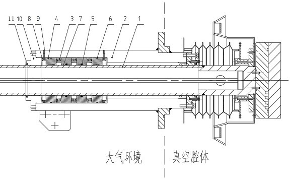
[0072] Such as figure 1 As shown, the present invention provides an axial magnetic fluid dynamic sealing structure, and the structure of the present invention is connected to the cavity of the vacuum precision casting furnace mold chamber as an example, including:

[0073] Shaft 1, which is arranged in a hollow housing 2, and can move back and forth in the housing 2;

[0074] At least three permanent magnets 3 are fixed side by side between the outer circle of the shaft 1 and the inner wall of the housing 2, and the total number of permanent magnets is an odd number;

[0075] A plurality of pole pieces 4, one pole piece 4 is arranged on both sides of each permanent magnet 3;

[0076] The baffle 5 is only arranged at the center of the inner circular surface of at least one of the two pole pieces 4 adjacent to the permanent magnet 3 in the middle position. It has no contact with the shaft 1 and a first gap is formed between it and the shaft 1. The preset gap is used to block t...

no. 2 example ;

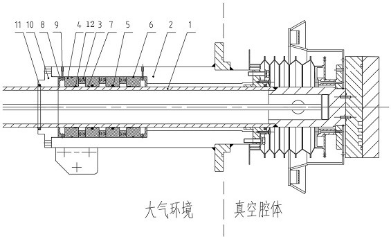
[0088] Such as figure 1 combine figure 2 As shown, the present invention provides an axial magnetic fluid dynamic sealing structure, and the structure of the present invention is connected to the cavity of the vacuum precision casting furnace mold chamber as an example, including:

[0089] Shaft 1, which is arranged in a hollow housing 2, and can move back and forth in the housing 2;

[0090] At least three permanent magnets 3 (permanent magnets 3 can be added in pairs according to the actual situation), fixed side by side between the outer circle of the shaft 1 and the inner wall of the housing 2;

[0091] A plurality of pole pieces 4, one pole piece 4 is arranged on both sides of each permanent magnet 3;

[0092] The baffle 5 is only arranged at the center of the inner circular surface of at least one of the two pole pieces 4 adjacent to the permanent magnet 3 in the middle position. It has no contact with the shaft 1 and a first gap is formed between it and the shaft 1. ...

no. 3 example ;

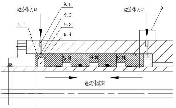
[0110] Such as image 3 As shown in 2, the present invention provides an axial magnetic fluid dynamic sealing structure, and the structure of the present invention is connected to the cavity of the vacuum precision casting furnace mold chamber as an example, including:

[0111] Shaft 1, which is arranged in a hollow housing 2, and can move back and forth in the housing 2;

[0112] At least three permanent magnets 3 (permanent magnets 3 can be added in pairs according to the actual situation), fixed side by side between the outer circle of the shaft 1 and the inner wall of the housing 2;

[0113] A plurality of pole pieces 4, one pole piece 4 is arranged on both sides of each permanent magnet 3;

[0114] The baffle 5 is only arranged at the center of the inner circular surface of at least one of the two pole pieces 4 adjacent to the permanent magnet 3 in the middle position. It has no contact with the shaft 1 and a first gap is formed between it and the shaft 1. The preset ga...


PUM


Abstract

The invention discloses an axial magnetic fluid dynamic seal structure. The axial magnetic fluid dynamic seal structure is characterized in that a shaft is arranged in a hollow shell; at least three permanent magnets are fixed between the excircle of the shaft and the inner wall of the shell in parallel; two sides of each permanent magnet are each provided with a pole shoe; a flow choking piece is only arranged at the center of the inner circular surface of at least one of two adjacent pole shoes of the permanent magnet in the middle position, and a first preset gap is formed between the flow choking piece and the shaft; first sealing elements are only arranged on the outer circular surfaces of the two pole shoes on the outermost side in the plurality of pole shoes; a magnetic fluid accommodating sealed space is formed between the pole teeth and the shaft, and a second preset gap is formed between each pole tooth and the shaft; magnetism isolating pieces are fixed to the axial outer sides of the two pole shoes on the outermost side in the plurality of pole shoes correspondingly; end covers are arranged at two ends of the hollow shell correspondingly; second sealing elements are arranged between the end covers and the shaft in a covering manner; and when the shell is vacuumized, the magnetic fluid accommodating sealed space is filled with a magnetic fluid, so that sealing is formed between the shaft and the pole teeth, and the first preset gap is smaller than the second preset gap.

Description

technical field [0001] The invention relates to the field of metallurgy, in particular to an axial magnetic fluid dynamic sealing structure for a crystal pulling mechanism of a vacuum precision casting furnace. Background technique [0002] Vacuum precision casting furnace is a vacuum casting equipment used in the fields of material science and metallurgical engineering technology. Under vacuum conditions, the precision casting furnace uses the principle of medium frequency induction heating to melt alloys with high content of active metals such as nickel, titanium, aluminum, etc. The ceramic mold quickly rises to the vacuum melting cavity for pouring, and then returns to the mold cavity for heat preservation and cooling to form, so that the casting can be completely smelted, poured and cooled to form without breaking the vacuum. It is mainly used on aerospace engine blades. The crystal pulling device is an important mechanism of the vacuum precision casting furnace. The st...

Claims


Application Information

Patent Timeline
Patent Type & Authority Applications(China)
IPC IPC(8): F16J15/43
Inventor 桂大兴刘捷王军
Owner SHANGHAI LIGOU SENSOR SCI & TECH
Why Eureka
Try Eureka