
Programmable controller and implementation method

A technology of programming controller and implementation method, applied in the direction of electrical program control, program control in sequence/logic controller, etc., can solve problems such as inability to meet the requirements of application scenarios, unexpandable operation of IO, fixed processing time, etc. Achieving the effect of friendly man-machine interface, saving foreign exchange, and low life cycle cost

Pending Publication Date: 2021-04-20
南京英特隆电子科技有限公司
View PDF1 Cites 0 Cited by
  • Summary
  • Abstract
  • Description
  • Claims
  • Application Information

AI Technical Summary

Problems solved by technology

However, in the design or production process, in some demanding applications, there are shortcomings such as fixed processing time, relatively fixed functions, no IO scalability, and inconvenient operation, which cannot meet the needs of more application scenarios.

Method used


Image

  • Programmable controller and implementation method
  • Programmable controller and implementation method
  • Programmable controller and implementation method

Examples


Embodiment 2

[0073] Such as Figure 20As shown, the application scene layout diagram of Embodiment 2 of the device of the present invention realizes the control of the material delivery trolley. The material delivery trolley stays in the loading area for 10S, then drives to the unloading area, and after staying for 10S, returns to the loading area again to form One cycle, the time for the feeding trolley to travel from the loading area to the unloading area is less than 1min, S1 is connected to the photoelectric switch of the material loading in place, and the feeding trolley is at low level when it arrives, S2 is connected to the unloading in place photoelectric switch, and the material transporting trolley is at low power when it arrives Ping, when H1 is turned on, the car moves backward, and when H2 is turned on, the car moves forward; to realize this function, according to the function definition of user parameters, the value of the working mode is 0, the value of the increment is 1, an...

Embodiment 3

[0077] Such as Figure 21 As shown, the application scene layout block diagram of Embodiment 3 of the device of the present invention, the automatic control program of the robotic arm, when the item on the conveyor belt A is detected, the robotic arm places the item from the conveyor belt A to the conveyor belt B, and the sensors used in this embodiment are all is active low.

[0078] Such as Figure 22 As shown, in the running sequence diagram of embodiment 3 of the device of the present invention, to realize this function, according to the user parameter function definition, the working mode value is 0, the number increment value is 1, and the time unit value is 0, and the user programming is as follows:

[0079] step Input detection conditions output control trigger time step time Judgment mechanism 1 none H2=1 1 1 0 2 S2=4 H2=2 1 999 2 3 none H1=1 1 1 0 4 S1=4 H1=2 1 999 2 5 none H4=1 1 1 0 6 S4=4 H...


PUM


Abstract

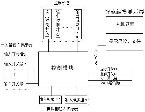
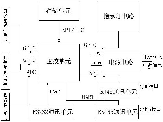
The invention provides a programmable controller and an implementation method. The programmable controller comprises a switching value input sensor, an analog quantity input sensor, an RJ45 communication interface, an RS485 communication interface, a starting switch K1, an emergency stop switch K0, control equipment, an intelligent touch display screen and a control module. The control module comprises a power supply circuit, a main control unit, a switching value input unit, a switching value output unit, an analog-digital interface unit, an RS232 communication unit, an RS485 communication unit, an RJ45 communication unit and a storage unit. For different application scenes, a user can carry out programming operation, a professional programming language or a downloading tool is not needed, a common user can select input, output and feedback variables for enabling, and the control function and the protection function of the system are achieved; a friendly human-computer interface is provided, so that the system cost is reduced to the maximum extent, the system reliability and stability are improved, and the requirement of a higher application scene can be met.

Description

technical field [0001] The invention relates to the fields of electrical control technology and computer control technology, in particular to a programmable controller and a realization method. Background technique [0002] In modern society, electrical control products have been developed for many years. Among programmable controller products, two types of product forms, PLC (Programmable Logic Controller, Programmable Logic Controller) and DDC (Direct Digital Control, Direct Digital Controller) have basically formed; The continuous development of informatization and intelligence in various industries has put forward higher requirements for controllers. New requirements have been put forward in terms of programmability, capacity, communication capabilities, and especially the ability to combine with information systems. The usage environment, usage method, and even user groups have changed a lot. [0003] In the fields of intelligent hardware, medical equipment, instrument...

Claims


Application Information

Patent Timeline
Patent Type & Authority Applications(China)
IPC IPC(8): G05B19/05
Inventor 不公告发明人
Owner 南京英特隆电子科技有限公司
Learn More