
Quick charger assembling method

A fast charging charger and the technology of the fast charging charger are applied in the direction of current collectors, circuit devices, battery circuit devices, etc., and can solve the problems of many assembly methods, low assembly efficiency, low heat dissipation efficiency of fast charging chargers, etc.

Pending Publication Date: 2021-04-20
GUANGZHOU ZHONGYIGUANG ELECTRONICS TECH
View PDF0 Cites 0 Cited by
  • Summary
  • Abstract
  • Description
  • Claims
  • Application Information

AI Technical Summary

Problems solved by technology

[0006] The purpose of the present invention is to provide a fast charging charger to solve the problem of low cooling efficiency of the fast charging charger in the prior art
[0007] Another object of the present invention is to provide a fast charging charger assembly method, which solves the problems of many steps and low assembly efficiency in the existing fast charging charger assembly method

Method used


Image

  • Quick charger assembling method
  • Quick charger assembling method
  • Quick charger assembling method

Examples


Embodiment Construction

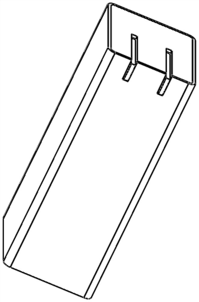
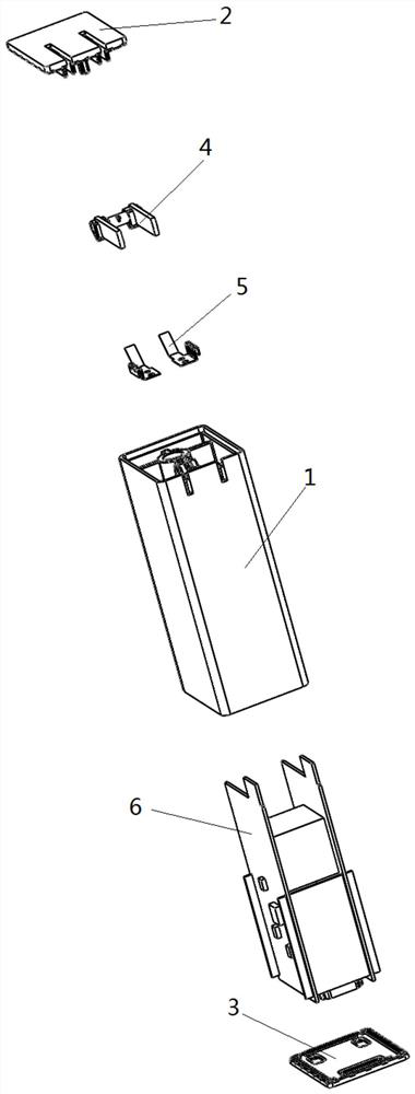
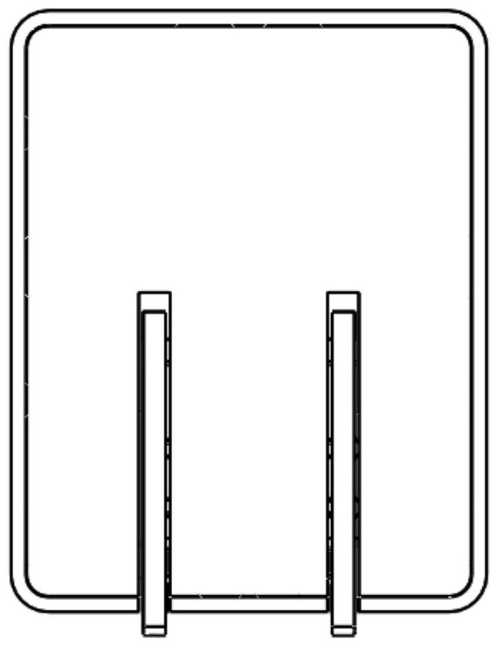
[0040] Such as Figure 1-11 The fast charging charger shown includes an upper cover 2 , a lower cover 3 , an AC plug 4 , a conductive shrapnel 5 , a PCB circuit board 6 and a housing body 1 .

[0041] A partition 7 is provided inside the housing main body 1 , so that the housing main body 1 is divided into an upper cavity and a lower cavity, and a conduction hole 11 is opened on the partition 7 . The PCB circuit board 6 includes a circuit board main body 601 and a circuit board connecting portion 602. The circuit board main body 601 is arranged in the lower cavity of the housing body 1, and the rest of the lower cavity is filled with a silica gel material (not shown in the figure). The material realizes good heat dissipation, and at the same time plays a role in fixing the circuit board and its electrical components; the circuit board connection part 602 is set through the conduction hole 11 of the interlayer 7, and the size, thickness and conduction of the circuit board conne...


PUM


Abstract

The invention provides a quick charger assembling method. The method comprises the following steps that (1) a PCB is arranged in a shell main body, wherein the PCB comprises a circuit board main body part and a circuit board connecting part; an interlayer is arranged in the shell main body to divide the shell main body into an upper cavity and a lower cavity, and the interlayer is provided with a through hole only allowing the circuit board connecting part to penetrate through; the circuit board main body part is arranged in the lower cavity, the circuit board connecting part penetrates through the through hole of the interlayer to enter the upper cavity, and the circuit board connecting part is connected with an alternating current plug arranged in the upper cavity; and ultrasonic welding is carried out on the upper cover plate and the shell main body; (2) the shell main body is inverted, and silica gel is poured into the lower cavity of the shell main body until the silica gel is cured; and (3) ultrasonic welding is carried out on the lower cover plate and the shell main body. According to the quick charger assembling method, the packaging process steps are greatly reduced, the production process is greatly simplified, and the assembling efficiency is improved.

Description

technical field [0001] The invention belongs to the technical field of electronic equipment, and in particular relates to a method for assembling a fast charging charger. Background technique [0002] A charger is a device that converts alternating current into low-voltage direct current. The charger is widely used in various fields, especially in the field of life, it is widely used in mobile phones, cameras and other common electrical appliances. The charger uses power electronic semiconductor devices to convert voltage and A static inverter device that converts alternating current with a fixed frequency into direct current is used everywhere in life and is an indispensable device. However, there are a series of defects in the common chargers on the market. For example, the charger is prone to heat during the charging process. Ordinary chargers cannot dissipate heat well, and the heat dissipation efficiency is too low. The heat dissipation problem of fast charging chargers...

Claims


Application Information

Patent Timeline
IPC IPC(8): H02J7/00H05K5/02H05K7/20
Inventor 王中于王生辉
Owner GUANGZHOU ZHONGYIGUANG ELECTRONICS TECH
Learn More