Circulating fluidized bed waste gas treatment device and system and waste gas treatment method

A waste gas treatment device and a technology of circulating flow, applied in separation methods, chemical instruments and methods, and dispersed particle separation, etc., can solve the problems of increasing the contact time between waste gas and adsorbent, poor waste gas effect, and low waste gas treatment efficiency.

Inactive Publication Date: 2021-04-23
JIANGSU NJU ENVIRONMENTAL TECH
View PDF7 Cites 0 Cited by
  • Summary
  • Abstract
  • Description
  • Claims
  • Application Information

AI Technical Summary

Problems solved by technology

[0005] Aiming at the low efficiency of waste gas treatment in the prior art, the present invention provides a circulating fluidized bed waste gas treatment device, which uses a fluidized plate to make the adsorbent entering the adsorption tower in a flowing state, increasing the contact time between the waste gas and the adsorbent, And the adsorbent can be dynamically regenerated in real time after entering the steam riser, which fully increases the utilization efficiency of the adsorbent, avoids the poor effect of using saturated adsorbents to treat waste gas, and solves the problem of low waste gas treatment efficiency

Method used


Image

  • Circulating fluidized bed waste gas treatment device and system and waste gas treatment method
  • Circulating fluidized bed waste gas treatment device and system and waste gas treatment method
  • Circulating fluidized bed waste gas treatment device and system and waste gas treatment method

Examples


Embodiment 1

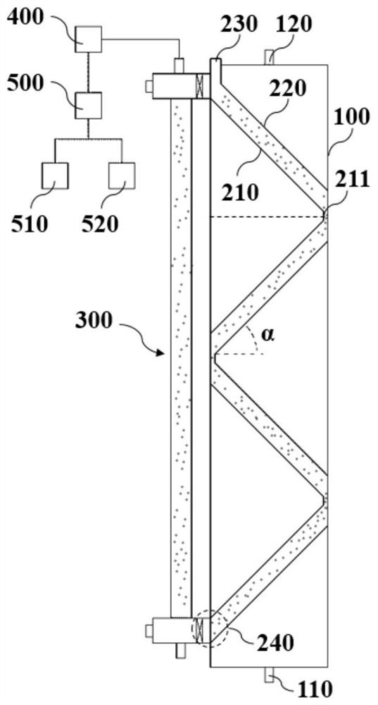
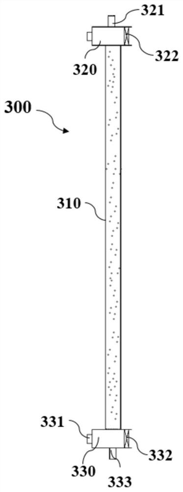
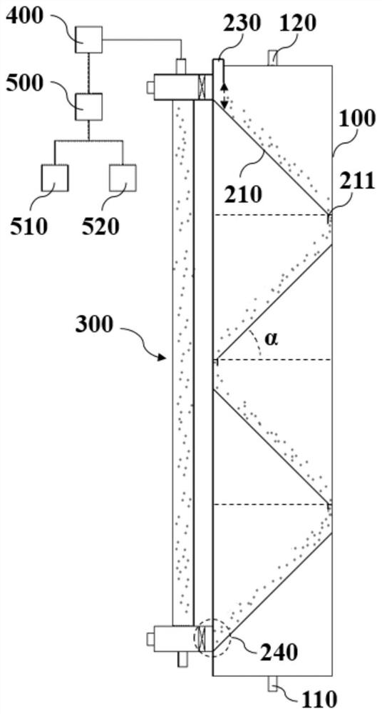
[0045] A circulating fluidized bed exhaust gas treatment device of the present invention includes an adsorption tower 100 , a fluidized plate 210 and a steam riser 300 . The bottom of the adsorption tower 100 is provided with an air inlet 110 and an adsorbent inlet 230 , and the bottom of the adsorption tower 100 is provided with a gas outlet 120 and an adsorbent outlet 240 . The diameter of the adsorption tower 100 is generally 0.6-1.2m, and the area of ​​the inclined fluidized plate 210 is adapted to the inner diameter of the adsorption tower 100 . Further illustrate, when the adsorption tower 100 is circular, the fluidized plate 210 is generally oval, and the peripheral side of the fluidized plate 210 is connected with the inner wall of the adsorption tower 100; when the adsorption tower 100 is rectangular, the fluidized plate 210 It is generally rectangular, and the peripheral side of the fluidized plate 210 is connected to the inner wall of the adsorption tower 100 .

[...

Embodiment 2

[0061] The basic content of this embodiment is the same as that of Embodiment 1, the difference is: in this embodiment, as image 3 As shown, there is no limiting plate 220 above the fluidization plate 210, the fluidization effect of this embodiment on resin is slightly worse than that of embodiment 1, and the effect of this embodiment on waste gas treatment is slightly worse than that of embodiment 1.


PUM


Abstract

The invention belongs to the field of waste gas treatment, and relates to a circulating fluidized bed waste gas treatment device and system and a waste gas treatment method. A fluidization plate is arranged in an adsorption tower, the fluidization plate is obliquely arranged in the adsorption tower, and air holes are distributed in the fluidization plate; a steam lifting pipe is arranged at the side part of the adsorption tower, one end of the steam lifting pipe is communicated with an adsorbent inlet, and the other end of the steam lifting pipe is communicated with an adsorbent outlet. The adsorbent entering the adsorption tower is in a flowing state through the fluidization plate, the contact time of waste gas and the adsorbent is prolonged, the adsorbent can be dynamically regenerated in real time after entering the steam lifting pipe, the utilization efficiency of the adsorbent is fully improved, and the situation that the waste gas treatment effect is poor when the adsorbent with saturated adsorption is used is avoided; and the problem of low waste gas treatment efficiency is solved.

Description

technical field [0001] The invention belongs to the field of exhaust gas treatment, and more specifically relates to a circulating fluidized bed exhaust gas treatment device, system and exhaust gas treatment method. Background technique [0002] At present, the exhaust gas treatment devices mainly include vertical, horizontal and annular adsorption devices, all of which have the problems of insufficient contact, short flow, and uneven distribution of resistance due to long time, and adopt a fixed bed structure, which is inefficient. The adsorption material cannot be regenerated in real time. Although there is a fluidized bed structure instead of a fixed bed, the control of the fluidized bed process is complicated, and improper operation can easily cause the loss of the adsorption material, so there are few practical applications. [0003] Patent No. CN105233625A, the patent of invention published on January 13, 2016 discloses a fluidized bed organic waste gas purification me...

Claims


Application Information

Patent Timeline
Patent Type & Authority Applications(China)
IPC IPC(8): B01D53/12
CPCB01D53/12
Inventor 周兵朱兆坚王宁阮志伟郭孝虎翟廷婷张炜铭
Owner JIANGSU NJU ENVIRONMENTAL TECH
Why Eureka
Try Eureka