
Waterproof and drainage device for wing and engine hanging butt joint based on 3D printing

A 3D printing and engine technology, used in wings, aircraft parts, transportation and packaging, etc., can solve problems such as electrical short circuit, seal failure, affecting flight safety, etc., to eliminate equipment failures and eliminate the risk of water leakage.

Pending Publication Date: 2021-04-23
XIAN AIRCRAFT DESIGN INST OF AVIATION IND OF CHINA
View PDF9 Cites 0 Cited by
  • Summary
  • Abstract
  • Description
  • Claims
  • Application Information

AI Technical Summary

Problems solved by technology

[0003] During the actual flight process, the gap between the separation surfaces may be large, exceeding the compensation range of the rubber profile through extrusion deformation, resulting in seal failure, and water will still leak into the interior of the aircraft structure from the gap between the bonding surfaces
There are many electrical, fuel, hydraulic and other system equipment and pipelines inside the engine suspension. Many equipment may cause electrical short circuit, material corrosion and other problems that affect flight safety due to water droplets.
[0004] Based on the above considerations, if only waterproofing is considered, the existing rubber and other sealing materials may not fully meet the design requirements

Method used


Image

  • Waterproof and drainage device for wing and engine hanging butt joint based on 3D printing
  • Waterproof and drainage device for wing and engine hanging butt joint based on 3D printing
  • Waterproof and drainage device for wing and engine hanging butt joint based on 3D printing

Examples


Embodiment 1

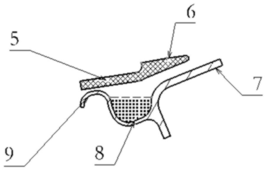
[0036] An anti-drainage device at the joint between the wing and the engine suspension, which is composed of a drainage groove 1, a waterproof rubber strip 2, a wing leading edge skin 3, and an engine suspension skin 4, and is characterized in that the skin at the leading edge of the wing 3 is connected to drain groove 1 by fasteners, and waterproof rubber strip 2 is connected to engine suspension skin 4 .

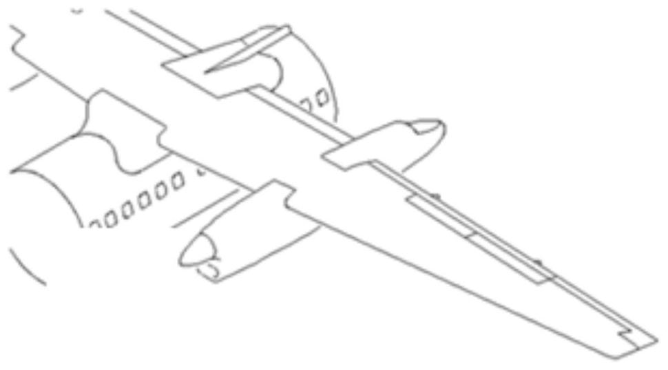
[0037] A. The 3D printing drainage groove 1 and the traditional waterproof rubber strip 2 are combined at the joint of the engine suspension at the leading edge of the wing, see Figure 1-2 ;

[0038] B. The waterproof rubber strip is a rubber part, which is used to realize the docking and sealing between the leading edge of the wing and the engine suspension skin, and offset the extrusion caused by relative deformation.

[0039] C. The cross-section of the waterproof rubber strip 2 is different along the intersecting line with the relative angle change between the shape ...


PUM


Abstract

The invention belongs to the field of aeronautical manufacturing, and relates to a waterproof and drainage device for a wing and an engine hanging butt joint based on 3D printing. The device comprises a drainage groove 1 and a waterproof rubber strip 2, wherein the drainage channel 1 is mounted on the side of the wing leading edge skin 3 and at the intersecting line position of the wing leading edge skin 3 and an engine hanger, and the drainage channel 1 is divided into a drainage section 101, a water diversion section 102, a leading-out section 103 and a fixed section 104; the drainage section 101 is located in a transverse area of an intersecting line, the water diversion section 102 is located in a longitudinal area, the leading-out section 103 is a leading-out pipe 11 led out from the tail end of the water diversion section 102, a water tank 8 is arranged on the drainage section 101, and a water diversion hole 10 communicated with the water tank at one end and a drainage pipe at the other end is formed in the water diversion section 102. The water tank 8 is used for receiving and collecting leaked water of the wing leading edge skin 3 and the engine hanging butt seam, guiding the leaked water to the water guide hole 10 and finally enabling the leaked water to flow out of the guide-out pipe 11; the waterproof rubber strip 2 is installed on the motor hanging side and the intersecting line position of the wing leading edge skin 3 and the engine hanging and used for sealing the butt joint of the wing leading edge skin 3 and the engine hanging under the normal condition.

Description

technical field [0001] The invention belongs to the field of aviation manufacturing, and relates to a 3D printing-based waterproof and drainage device for the joint between a wing and an engine suspension. Background technique [0002] For a propeller aircraft with a wing suspension, the upper surface of the engine suspension extends to the shape of the leading edge of the wing, and there is no mechanical connection between the two large parts, and there will inevitably be deformation inconsistencies during flight, resulting in inability to separate the separation surfaces. Achieving a seal. The waterproof and drainage design of the existing aircraft here is mainly based on waterproofing. A circle of rubber profiles is arranged on the edge of the engine suspension along the intersecting line with the shape of the leading edge of the wing, and the waterproof and pneumatic sealing is realized through the extrusion of the rubber profiles. [0003] During the actual flight, the...

Claims


Application Information

Patent Timeline
Patent Type & Authority Applications(China)
IPC IPC(8): B64C3/32
CPCB64C3/32
Inventor 马存瑞党军辉王方宇杨燕
Owner XIAN AIRCRAFT DESIGN INST OF AVIATION IND OF CHINA
Learn More