
Rail transit obstacle removing device

A barrier-removing device and rail transit technology, applied in the field of rail transit, can solve the problems of manual adjustment, weak engine operation, troublesome operation, etc.

Active Publication Date: 2021-04-23
CHONGQING VOCATIONAL COLLEGE OF TRANSPORTATION
View PDF11 Cites 2 Cited by
  • Summary
  • Abstract
  • Description
  • Claims
  • Application Information

AI Technical Summary

Problems solved by technology

When the fuel system is in different altitude environments, due to the different external air pressure, the amount of fuel required by the fuel system is also different. When working in different altitude environments, it is necessary to manually adjust the throttle valve so that the throttle valve can Adjust the fuel flow according to the difference, because the flow is manually adjusted, the operation is more troublesome
In addition, if the fuel flow is not adjusted or the adjustment is inaccurate, the fuel flow in the fuel system will not match the normal working fuel flow, which will easily cause flameout, engine running weak and other phenomena, thus affecting the normal operation of the fuel system

Method used


Image

  • Rail transit obstacle removing device

Examples


Embodiment 1

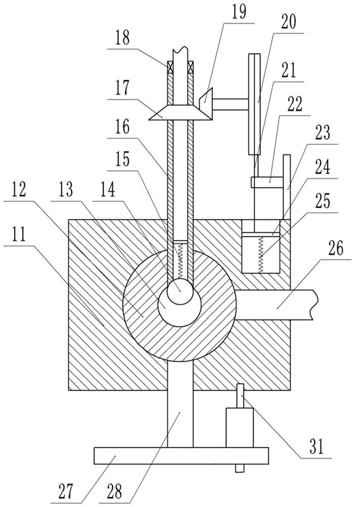
[0018] Basic as attached figure 1 Shown: rail transit obstacle removal device, which can be specifically a repair vehicle, including a fuel system, which includes a fuel tank, an oil filter, a fuel pump, a one-way valve, an engine, a solenoid valve, a throttle valve, and a fuel pipeline. This implementation The fuel system in the example belongs to the prior art and is used to drive the wrecker to work. It is relatively common in existing wreckers, construction cranes and automobiles that use fuel as power, and will not be repeated here. In this embodiment, the throttle valve in the fuel system is mainly improved, specifically: the throttle valve includes a housing 11, a ball cavity is provided in the housing 11, a ball 12 is connected to the ball cavity in rotation, and the ball 12 is provided with There is an oil hole 13, and the housing 11 is provided with a horizontally arranged oil outlet 26 and two vertical passages, the two passages are respectively located on the upper...

Embodiment 2

[0026] The difference between the embodiment and the embodiment 1 is that, on the basis of the embodiment 1, only the positions of the two ends of the stay cord 21 are exchanged, that is, the end of the stay cord 21 connected to the weight 22 in the embodiment 1 is now connected to the piston. 24 is connected, and the end that stay cord 21 is connected with piston 24 is connected with weight 22 at this moment. In this way, when the weight 22 slides, the direction of rotation of the adjusting disc 20 is opposite to that of Embodiment 1, so that the angle between the oil hole 13 on the ball 12 and the oil outlet 26 becomes smaller after the working altitude of the device becomes higher. , the degree of communication between the oil hole 13 and the oil outlet passage 26 becomes larger, so that the flow rate of fuel entering the oil outlet passage 26 becomes larger. When the working altitude of the device becomes lower, the angle between the oil hole 13 on the sphere 12 and the oi...


PUM


Abstract

The invention relates to the field of rail transit, in particular to a rail transit obstacle removing device which comprises a fuel oil system, the fuel oil system comprises a throttling valve, the throttling valve comprises a shell, a ball cavity is formed in the shell, a ball body is rotatably connected in the ball cavity, an oil hole is formed in the ball body, and the shell is provided with an oil outlet path and two channels; the ball body is connected with an oil inlet pipe communicating with the oil hole, a rotating shaft is connected to the ball body, and the end, away from the ball body, of the rotating shaft is fixedly connected with a rotating disc; a rotary adjusting disc is arranged above the shell, and a bevel gear set is connected between the adjusting disc and the oil inlet pipe; a piston cavity is formed in the shell, a piston is connected into the piston cavity in a sliding mode, a first tension spring is connected between the piston and the bottom of the piston cavity, and the interior of a closed space formed by the piston and the piston cavity is arranged in a vacuum mode; and a pull rope is connected to the piston, the end, away from the piston, of the pull rope is wound around the adjusting disc and is connected with a counter weight. According to the scheme, it is achieved that the throttling valve in the fuel oil system can be automatically adjusted in different altitude environments.

Description

technical field [0001] The invention relates to the field of rail traffic, in particular to a rail traffic obstacle removal device. Background technique [0002] At present, rail trains are a common way for people to travel. We will take trains, high-speed rails and other means of transportation for long-distance travel between cities. In winter, there will inevitably be snow and ice on the track, which will affect the running of the rail train. layer to clean up. [0003] The current rail transit obstacle removal device is a wrecker. When encountering ice and snow, the power system will fail. Therefore, in order to ensure the smooth work of the wrecker, the wrecker is driven by the fuel system when it is working. rather than powered by electricity. [0004] The fuel system of the wrecker mainly includes fuel tanks, oil filters, fuel pumps, check valves, engines, solenoid valves, throttle valves, and fuel pipelines. When the fuel system is in different altitude environme...

Claims


Application Information

Patent Timeline
Patent Type & Authority Applications(China)
IPC IPC(8): F16K15/18F16K5/06F16K35/02F16K31/14F16K31/163F02M37/00B61D15/00
CPCF16K5/0605F16K5/0647F16K35/025F16K31/14F16K31/1635F02M37/0023B61D15/00F16K15/1848F16K15/1823
Inventor 杨昌休何帆熊伟
Owner CHONGQING VOCATIONAL COLLEGE OF TRANSPORTATION
Learn More