Refrigerator
A technology for refrigerators and cabinets, which is applied in the field of dust removal devices for refrigerator condensers. It can solve problems such as poor heat transfer effects of condensers, dust accumulation in condensers, and increased energy consumption of refrigerators. It achieves simple structure, effective dust removal, and The effect of high resource utilization
- Summary
- Abstract
- Description
- Claims
- Application Information
AI Technical Summary
Problems solved by technology
Method used
Image
Examples
Embodiment 1
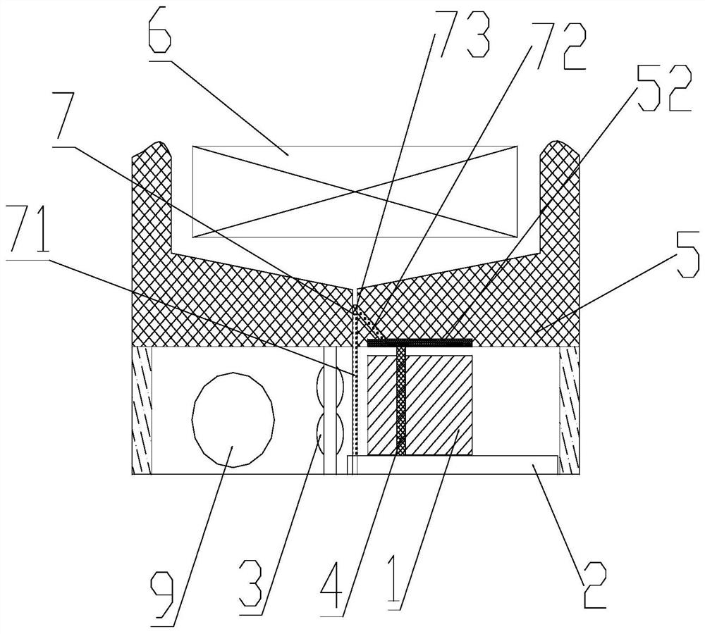
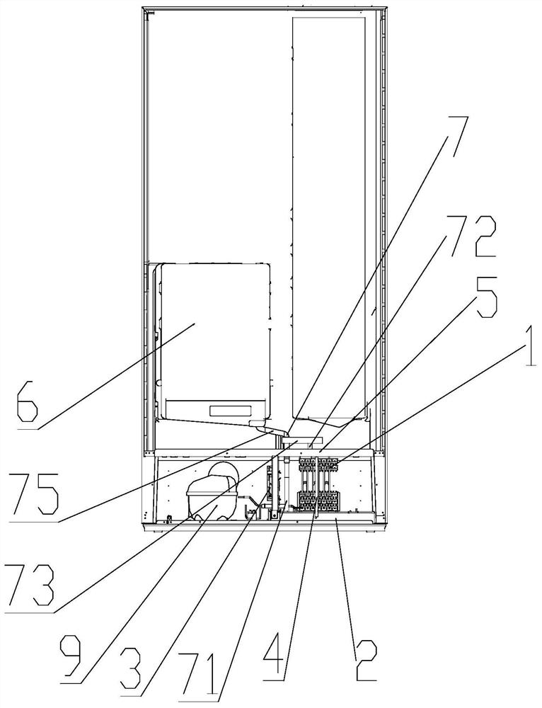
[0052] Such as Figure 2-11 Shown, a kind of refrigerator comprises:
[0053] A box body, the box body has a low-temperature storage space;
[0054] A compressor compartment, the compressor compartment is located outside the box, and the compressor compartment is provided with a compressor 9, a condenser 1 and a first water receiving tray 2 located on the lower side of the condenser 1;
[0055] The box body is provided with a drainage system 7 communicating with the compressor compartment, and the drainage system 7 is communicating with the first water receiving tray 2 through a drainage pipe. The refrigerator also includes:
[0056] The second water receiving tray 52 arranged on the upper side of the condenser 1, the drainage system 7 extends to the upper end of the second water receiving tray 52, the drainage system 7 and the second water receiving tray 52 The second water receiving tray 52 is provided with a plurality of drainage holes through the drain pipe, and the cond...
Embodiment 2
[0069] In order to further solve the problem that during the use of the existing refrigerator, dust and dust will appear on the surface of the condenser, resulting in poor heat exchange effect of the condenser and increased energy consumption of the refrigerator, on the basis of Example 1, the implementation The refrigerator described in Example 1 is further optimized:
[0070] Specifically, such as Figure 2~3 As shown, the drainage system 7 includes a first connecting pipe 75, a drainage branch 71, a dust removal branch 72 and a reversing valve 73, the reversing valve 73 is a two-position three-way reversing valve, and the first connection Both ends of the pipe 75 are respectively connected to the water outlet of the evaporator 6 and the water inlet of the reversing valve 73; one end of the drainage branch 71 is connected to one of the water outlets of the reversing valve 73, so that The other end of the drainage branch 71 is connected with the first water receiving tray 2;...
Embodiment 3
[0082] In order to further solve the problem that during the use of the existing refrigerator, dust and dust will appear on the surface of the condenser, resulting in poor heat exchange effect of the condenser and increased energy consumption of the refrigerator, on the basis of Example 1, the implementation The refrigerator described in Example 1 is further optimized:
[0083] Specifically, such as Figure 4~5As shown, the drainage system 7 includes a circulation branch 74 and a second connecting pipe 76, and the two ends of the second connecting pipe 76 are connected to the water outlet of the evaporator 6 and the water inlet of the first water receiving tray 2 respectively. The two ends of the circulation branch 74 are respectively connected to the water outlet of the first water receiving pan 2 and the second water receiving pan 52, and the defrosting water on the evaporator 6 passes through the second water receiving pan 52. The connecting pipe 76 flows into the first wa...
PUM
 Abstract
Description
Claims
Application Information
 - R&D
- Intellectual Property
- Life Sciences
- Materials
- Tech Scout
- Unparalleled Data Quality
- Higher Quality Content
- 60% Fewer Hallucinations
Browse by: Latest US Patents, China's latest patents, Technical Efficacy Thesaurus, Application Domain, Technology Topic, Popular Technical Reports.
© 2025 PatSnap. All rights reserved.Legal|Privacy policy|Modern Slavery Act Transparency Statement|Sitemap|About US| Contact US: help@patsnap.com


