Single-photon imaging radar system

An imaging radar and single-photon technology, which is applied in radio wave measurement systems, electromagnetic wave re-radiation, and utilization of re-radiation, etc., can solve problems such as increased noise, complex overall structure, and large laser power.

Pending Publication Date: 2021-04-23
UNIV OF SCI & TECH OF CHINA
View PDF0 Cites 6 Cited by
  • Summary
  • Abstract
  • Description
  • Claims
  • Application Information

AI Technical Summary

Problems solved by technology

The above technologies realize three-dimensional imaging of objects at a distance of 10km. However, they all use large-aperture telescopes as beam transceiver devices, and their overall structure is complex and bulky. At the same time, the above technologies solve the problem of beam receiving efficiency, or use large Laser power, or use a long integration time, but these me

Method used


Image

  • Single-photon imaging radar system
  • Single-photon imaging radar system
  • Single-photon imaging radar system

Examples


Embodiment Construction

[0021]Hereinafter, an embodiment of the present disclosure will be described with reference to the accompanying drawings. It should be understood, however, that these descriptions are merely exemplary, and not to limit the scope of the disclosure. In the following detailed description, many of the specific details are set forth to provide a comprehensive understanding of the embodiments of the present disclosure. However, it is apparent that one or more embodiments may be implemented without these specific details. Further, in the following description, a description of the well-known structure and techniques is omitted to avoid unnecessarily obscuring the concepts of the present disclosure.

[0022]The terminology used herein is merely to describe specific embodiments, and is not intended to limit the disclosure. The term "comprising", "comprising", including,, or the like, indicating the presence of the features, steps, operations, and / or components, but does not exclude presence o...


PUM


Abstract

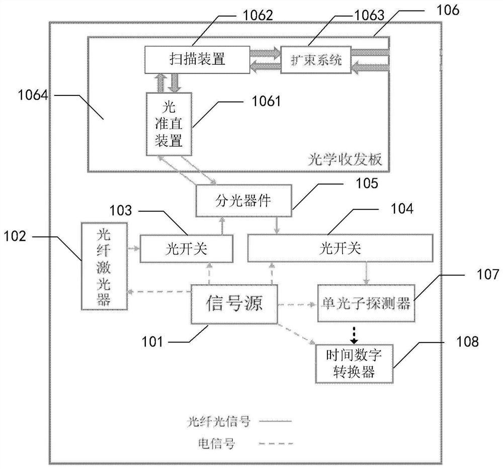
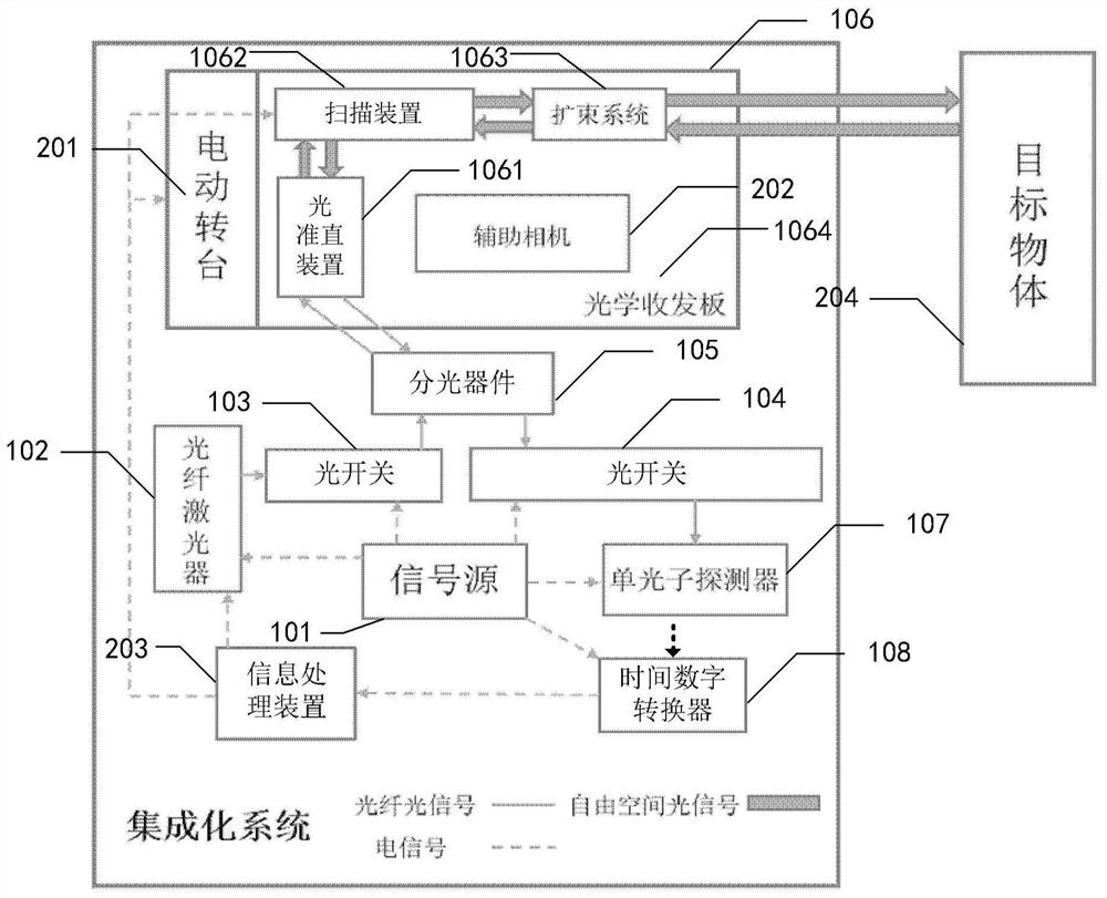
The invention provides a single-photon imaging radar system. The system comprises a signal source which is used for generating a synchronization signal and a gating signal; a fiber laser is used for receiving the synchronizing signal and responding to the synchronizing signal to emit a laser pulse; a first optical switch and a second optical switch are used for receiving the gating signal and responding to the gating signal to be opened or closed so as to control whether the laser pulse passes through the optical switches or not; a light splitting device is used for receiving the laser pulse transmitted by the first optical switch and transmitting the laser pulse to the optical transceiver board, or used for receiving the laser pulse transmitted by the optical transceiver board and transmitting the laser pulse to the second optical switch; an optical transceiver board; a single-photon detector is used for receiving the gating signal and the laser pulse, opening or closing in response to the gating signal, generating a detection signal in response to the laser pulse when the single-photon detector is opened, and transmitting the detection signal to the time-to-digital converter; and a time-to-digital converter is used for receiving the synchronization signal and the detection signal and recording time information.

Description

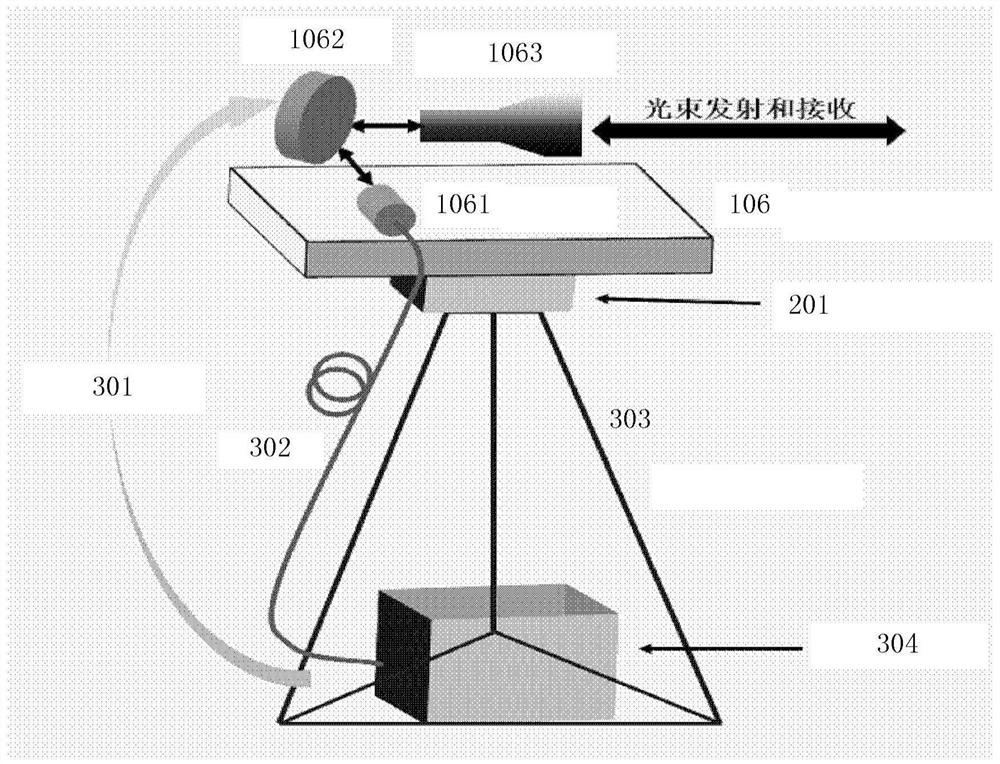
Technical field[0001]The present disclosure relates to the field of laser radar, and more particularly to a single photon imaging radar system.Background technique[0002]Laser imaging radar is one of the most accurate three-dimensional imaging techniques of application, which is the main principle that the laser pulse is transmitted to the target area and receives the echo, and the distance between the target and the emission point is obtained by measuring the flight time of the photon. A three-dimensional image of the target object is obtained by scanning a target area.[0003]The three-dimensional imaging system completed by the three-dimensional imaging system, such as the study team of China University of Science and Technology, China, or the three-dimensional pulse laser imaging system completed by the University of Herry Watt University. The above technique achieves three-dimensional imaging of 10km distance external object, however they have a large diameter telescope as a beam ...

Claims


Application Information

Patent Timeline
IPC IPC(8): G01S7/481G01S7/483G01S17/89
CPCG01S7/481G01S7/483G01S17/89
Inventor 徐飞虎黎正平蒋鹏宇潘建伟
Owner UNIV OF SCI & TECH OF CHINA
Why Eureka
Try Eureka