Parabolic cylindrical surface deployable antenna adopting Y-shaped rib cable net, control method and application

A parabolic cylinder, ribbed cable net technology, applied in antennas, folded antennas, rotating antennas, etc., can solve problems such as reducing the overall quality, and achieve the effects of high structural rigidity, high storage ratio, strong expandability and adaptability

Active Publication Date: 2021-04-27
XIDIAN UNIV
View PDF8 Cites 6 Cited by
  • Summary
  • Abstract
  • Description
  • Claims
  • Application Information

AI Technical Summary

Problems solved by technology

[0004] Through the above analysis, the problems and defects of the existing technology are: the current parabolic antenna cannot be designed with a large aperture due to factors such as storage ratio, quality or surface accuracy.
[0005] The difficulty in solving the above problems and defects is: when designing a large-diameter deployable antenna, while ensuring the accuracy of the antenna profile and structural rigidity, it is necessary to find ways to improve the antenna storage ratio and reduce the overall quality, which puts more stringent requirements on the antenna structure design. Require

Method used


Image

  • Parabolic cylindrical surface deployable antenna adopting Y-shaped rib cable net, control method and application
  • Parabolic cylindrical surface deployable antenna adopting Y-shaped rib cable net, control method and application
  • Parabolic cylindrical surface deployable antenna adopting Y-shaped rib cable net, control method and application

Examples


Embodiment Construction

[0033] In order to make the object, technical solution and advantages of the present invention more clear, the present invention will be further described in detail below in conjunction with the examples. It should be understood that the specific embodiments described here are only used to explain the present invention, not to limit the present invention.

[0034] Aiming at the problems existing in the prior art, the present invention provides a deployable antenna using a Y-shaped rib cable net parabolic cylinder, a control method and an application. The present invention will be described in detail below with reference to the accompanying drawings.

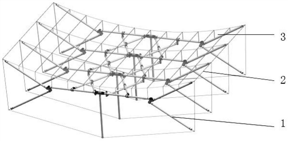
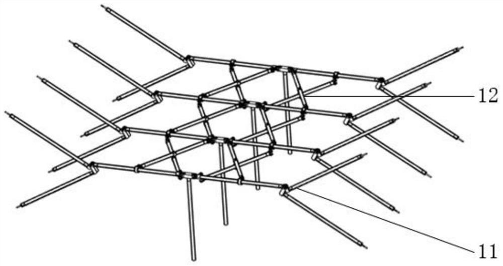
[0035] Such as figure 1 As shown, the cable-net parabolic cylindrical deployable antenna using Y-shaped ribs provided by the present invention is mainly composed of a Y-shaped rib supporting truss 1 , a cable net 2 and a wire mesh 3 . Among them, the Y-shaped rib support truss 1 is used as the support and deployment mechanism of...


PUM


Abstract

The invention belongs to the technical field of satellite-borne deployable antennas, and discloses a Y-shaped rib cable net parabolic cylinder deployable antenna, a control method and application, which are composed of a Y-shaped rib support truss, a cable net and a metal wire net. The Y-shaped rib supporting truss is composed of a Y-shaped rib deployable unit in the parabola direction and a shear type deployable unit in the baseline direction, and the Y-shaped rib deployable unit and the shear type deployable unit are connected through a fixed hinge joint and a sliding hinge joint at the tail end of the shear type deployable unit. End points on the two sides of the cable net and nodes on the lower side of the cable net are connected with the Y-shaped rib deployable units, and a needed parabolic cylinder shape is formed through pretension design. The metal wire mesh is laid on the cable mesh to receive and reflect electromagnetic waves. The Y-shaped rib supporting truss serves as a supporting and unfolding mechanism of the cable net parabolic cylinder deployable antenna, and smooth unfolding of the antenna in the parabola direction and the baseline direction is achieved under combined driving of the torsional spring and the inhaul cable. The folding mechanism is large in unfolding caliber, high in storage ratio, high in unfolding reliability and high in structural expansibility.

Description

technical field [0001] The invention belongs to the technical field of space-borne deployable antennas, and in particular relates to a deployable antenna adopting a Y-shaped rib cable net parabolic cylinder, a control method and an application. Background technique [0002] In recent years, spaceborne antennas have been widely used in important fields such as electronic reconnaissance, resource detection, and long-distance communication, and have shown a development trend of large aperture, high precision, high storage ratio, and light weight. Due to the limitation of the rocket's carrying capacity and carrying cost, the previous solid-surface reflector antennas can no longer meet the requirements, so large-scale spaceborne antennas must have the characteristics of expandability. [0003] At present, scholars at home and abroad have carried out a lot of research work on the rotating paraboloid deployable antenna and achieved gratifying results, but there are not many studies...

Claims


Application Information

Patent Timeline
Patent Type & Authority Applications(China)
IPC IPC(8): H01Q1/08H01Q15/16
CPCH01Q1/08H01Q1/084H01Q15/161
Inventor 张树新叶靖张顺吉段宝岩闫雷东李昊天潘海洋
Owner XIDIAN UNIV
Why Eureka
Try Eureka