Pedicle screw rod internal fixing device taking positioning pin as inner core

A technology of pedicle screw and fixation device, applied in the field of pedicle screw, can solve the problems of unfavorable connecting rod placement composition, nerve root paralysis or paraplegia, prolonged operation time and the like

Active Publication Date: 2021-04-30
THE AFFILIATED SIR RUN RUN SHAW HOSPITAL OF SCHOOL OF MEDICINE ZHEJIANG UNIV
View PDF9 Cites 0 Cited by
  • Summary
  • Abstract
  • Description
  • Claims
  • Application Information

AI Technical Summary

Problems solved by technology

If the screw is placed by hand, the displacement of the screw track is likely to cause the deviation of the track of the pedicle screw. In severe cases, the spinal cord and nerve root may be stimulated by the pedicle screw breaking into the spinal canal, causing catastrophic symptoms such as cerebrospinal fluid leakage, nerve root paralysis, or paraplegia. as a result of
In addition, repeated fluoroscopy during the operation prolongs the entire operation time and increases the risk of infection during the operation; the other is the percutaneous Sextant pedicle screw internal fixation system produced by the foreign shufamo company. Its pedicle screw Part is hollow design, but the U-shaped part at the top is short, which is not conducive to the placement of connecting rods

Method used


Image

  • Pedicle screw rod internal fixing device taking positioning pin as inner core
  • Pedicle screw rod internal fixing device taking positioning pin as inner core
  • Pedicle screw rod internal fixing device taking positioning pin as inner core

Examples


Embodiment 1

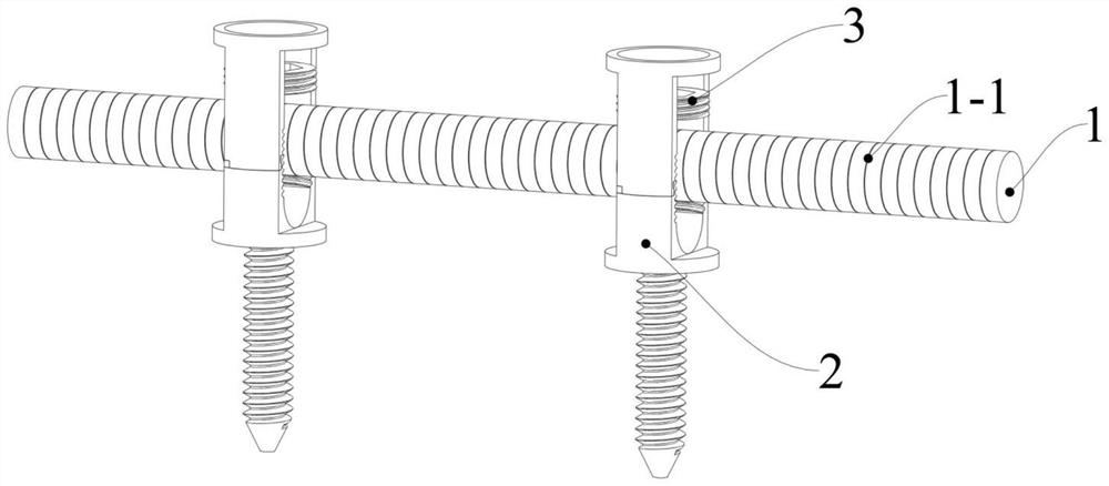
[0027] Such as figure 1 As shown, a pedicle screw rod internal fixation device with a positioning pin as the inner core includes a connecting rod 1 , two pedicle screw bodies 2 , two locking screws 3 and two pins 4 . When in use, two pedicle screw main bodies 2 are arranged at intervals on the connecting rod 1 , and are respectively fixed to the connecting rod 1 by corresponding locking screws 3 . The connecting rod 1 is cylindrical; the side of the connecting rod 1 is arranged in sequence along the length direction with circular scale lines 1-1, and is provided with a scale mark, which is convenient for the doctor to quickly read the two pedicle screw main bodies 2 the distance between. One end of the pin 4 is sharp and can penetrate into the position where the pedicle screw needs to be implanted in the patient in advance, so as to provide positioning for the main body 2 of the pedicle screw.

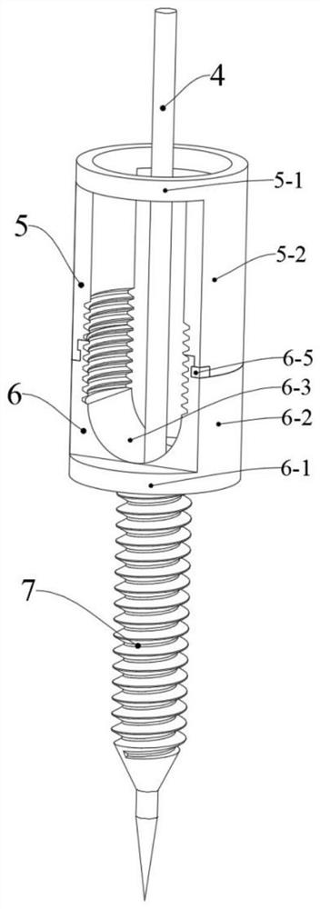
[0028] Such as figure 2 , 3 , 4 and 5, the pedicle screw body 2 includes a di...

Embodiment 2

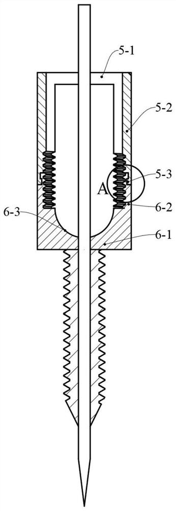
[0040] Such as Figure 7 As shown, the difference between this embodiment and Embodiment 1 is that the disengagement part 5 and the locking part 6 of the pedicle screw main body 2 are not connected by screwing. The disengagement part 5 is arranged on the outer side of the locking part 6, and is composed of an integrally formed outer retaining ring 5-1 and two disengagement ears 5-2. The inner ends of the two disengagement ears 5-2 and the outer ends of the two locking ears 6-2 are respectively integrally formed through the fracture connecting portion 2-1. A breaking groove is provided on the outside of the fracture connection part 2-1; the doctor can break the connection between the disengagement part 5 and the locking part 6 by pressing from the outside.


PUM


Abstract

The invention discloses a pedicle screw rod internal fixing device with a positioning pin as an inner core. The pedicle screw rod internal fixing device comprises a connecting rod, a pedicle screw body and a pin. The connecting rod is in a cylindrical shape; scale marks are arranged on the side face of the connecting rod. The pedicle screw main body comprises a separation part, a locking part and a screw part which are connected in sequence. The locking part comprises a locking disc and two locking lugs. The two locking lugs are connected with the edges of the two sides of the locking disc respectively. After thepedicle screw rod internal fixing device is installed on a human body, the connecting rod is located between the two locking lugs. The locking part can be fixed with and separated from different positions of the connecting rod. the end part of the outer end of the screw part is sharp. The pedicle screw main body is provided with a center hole penetrating through the screw part and the locking disc and used for being matched with a pin. The separation part can be separated from the locking part.

Description

technical field [0001] The invention belongs to the technical field of pedicle screws, in particular to a pedicle screw rod internal fixation system with a positioning tip as the inner core, which is mainly used in thoracolumbar fractures, intervertebral disc herniation, spinal stenosis, and spinal deformity , spinal infection, spinal tumors and other orthopedic diseases that require internal fixation with a screw-rod system. Background technique [0002] At present, there are two kinds of pedicle screws that have been publicly used at home and abroad: one is conventional pedicle screws, such as GSS thoracolumbar internal fixation system, USS screw-rod system, and domestic systems such as Kehui and Weigao. It is a solid screw. When PLIF, TLIF, or MIS-TLIF minimally invasive surgery is used to place pedicle screws, there are no guiding signs during the operation, and repeated fluoroscopy with a C-arm X-ray machine is required. If the screw is placed by hand, the displacement...

Claims


Application Information

Patent Timeline
Patent Type & Authority Applications(China)
IPC IPC(8): A61B17/70
CPCA61B17/7034A61B17/7002
Inventor 谢子昂徐文斌宁磊范顺武
Owner THE AFFILIATED SIR RUN RUN SHAW HOSPITAL OF SCHOOL OF MEDICINE ZHEJIANG UNIV
Why Eureka
Try Eureka