
Communication laser temperature control coupling welding device

A welding device and laser technology are applied in the field of optical communication to achieve the effects of reducing repair costs, avoiding material loss and labor loss, and stabilizing fiber input power.

Inactive Publication Date: 2021-04-30
大连优欣光科技股份有限公司
View PDF6 Cites 0 Cited by
  • Summary
  • Abstract
  • Description
  • Claims
  • Application Information

AI Technical Summary

Problems solved by technology

In order to achieve temperature control coupling, the cooperation of temperature control equipment is required. At present, there is no coupling welding machine that can perform temperature adjustment and control.

Method used


Image

  • Communication laser temperature control coupling welding device
  • Communication laser temperature control coupling welding device
  • Communication laser temperature control coupling welding device

Examples


Embodiment

[0034] The device of the present invention is used for temperature-controlled coupling welding: through temperature adjustment, the wavelength is locked, and then the fiber input power is welded to 2.5dBm, and the final inspection test is adjusted to the center wavelength. At different temperatures, the fiber input power is 2.5dBm, which can still guarantee normal temperature The power into the fiber when coupled at 25°C is 2.5dBm.

[0035] Table 2 temperature control coupling welding data of the present invention

[0036] parameter 1 2 3 4 5 Coupling welding into fiber power 2.5dBm 2.5dBm 2.5dBm 2.5dBm 2.5dBm final test temperature 50.5℃ 48.5℃ 47.2℃ 49℃ 50℃ Final test fiber input power 2.5dBm 2.5dBm 2.5dBm 2.5dBm 2.5dBm

[0037] By comparing the data of the comparison example with the example, it can be seen that the center wavelength is locked by temperature control during the coupling welding process, and the weldin...


PUM


Abstract

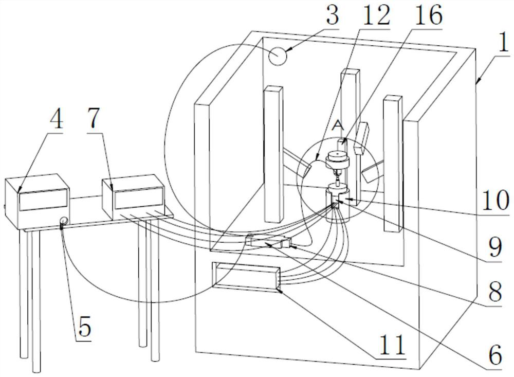
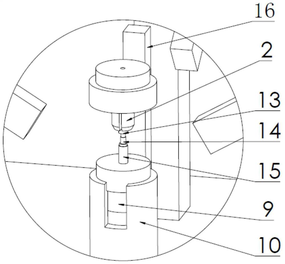
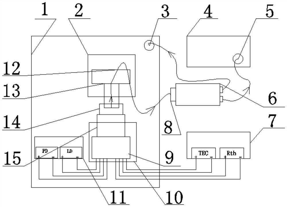
The invention belongs to the technical field of optical communication, and relates to a communication laser temperature control coupling welding device. The communication laser temperature control coupling welding device comprises a coupling welding machine, a wavelength meter, an optical branching device, a temperature controller, an FC-to-FC flange, an electric insertion core, an insertion pin and a Z-shaped sleeve. According to the communication laser temperature control coupling welding device, the laser is controlled at the central wavelength through temperature adjustment, and then the temperature is locked, and coupling welding is carried out at the temperature, so that the stability of the fiber-in power of the whole batch of products at the central wavelength is realized, and the accurate output of the fiber-in power of the laser at the central wavelength is realized.

Description

technical field [0001] The invention belongs to the technical field of optical communication, and relates to a communication laser temperature control coupling welding device. Background technique [0002] At present, the 5G network is developing rapidly, and the performance requirements for communication lasers are constantly improving, mainly to control the power coupled into the fiber at the central wavelength. The traditional coupling method does not add temperature control. Because the temperature has a great influence on the optical power, often The required wavelength cannot be achieved at room temperature and the center wavelength temperature of each product is different, resulting in a large fluctuation in optical power, with a maximum difference of 3dBm. [0003] For example, at the center wavelength required by the customer, the fiber input optical power is 2.5dBm. If the coupling is traditional, the traditional coupling is coupling at room temperature, but the te...

Claims


Application Information

Patent Timeline
Patent Type & Authority Applications(China)
IPC IPC(8): B23K26/21B23K26/70
CPCB23K26/21B23K26/70
Inventor 李志超廖传武宋小飞王志文侯炳泽
Owner 大连优欣光科技股份有限公司
Learn More