Strip soap processing and cutting device
A cutting device and soap technology, applied in metal processing, cutting soap and other directions, can solve the problems of decreased work efficiency, inconsistent soap specifications, etc., and achieve the effect of improving work efficiency
- Summary
- Abstract
- Description
- Claims
- Application Information
AI Technical Summary
Problems solved by technology
Method used
Image
Examples
Embodiment 1
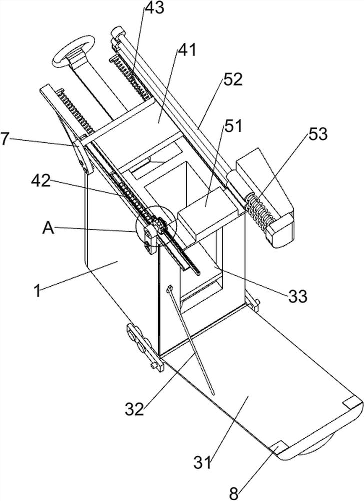
[0042] A long bar soap processing and cutting device, such as figure 1 As shown, it includes a workbench 1, a briquetting block 2, a transport mechanism 3, a cutting mechanism 4, and a pushing mechanism 5. The upper inner top wall of the workbench 1 is connected with a briquetting block 2, and the workbench 1 is connected with a transport mechanism 3. A cutting mechanism 4 is connected to the top of the workbench 1 , and a pusher mechanism 5 is connected between the cutting mechanism 4 and the workbench 1 .
[0043] When people need to cut soap, they first open the parts of the transport mechanism 3, then place the soap on the parts of the transport mechanism 3, so that the top of the soap fits the pressing block 2, then close the parts of the transport mechanism 3, and then move The parts of the cutting mechanism 4 make the parts of the cutting mechanism 4 cut the soap, and simultaneously drive the parts of the pushing mechanism 5 to push out the cut soap.
Embodiment 2
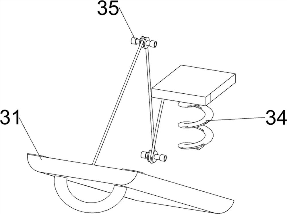
[0045] On the basis of Example 1, such as Figure 2-4 As shown, the transportation mechanism 3 includes a side plate 31, a stay rope 32, a support block 33, a first spring 34 and a guide wheel 35, and the lower part of the right side of the workbench 1 is rotatably connected with the side plate 31, and the right side of the workbench 1 is up and down. Both sides are rotatably connected with wire pulleys 35, the inside of the workbench 1 is slidably connected with a support block 33, and a pull rope 32 is connected between the bottom of the support block 33 and the lower left side of the side plate 31, and the pull rope 32 bypasses two wires A first spring 34 is connected between the wheel 35 , the middle of the bottom of the support block 33 and the inner bottom wall of the workbench 1 .
[0046] When people need to place soap, first the side plate 31 is rotated to the right, and the stay cord 32 is driven to pull down, so that the support block 33 moves downward, and the firs...
Embodiment 3
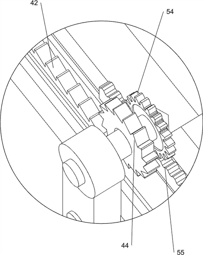
[0050] On the basis of Example 2, such as figure 1 , image 3 with Figure 4 As shown, the pushing mechanism 5 includes a push block 51, a guide rod 52, a third spring 53, a gear 54 and a second rack 55, and the upper and lower sides of the workbench 1 are connected with a guide rod 52 up and down, between the guide rods 52 Slidingly connected with a push block 51, the front side of the push block 51 is connected with a second rack 55, the rear side of the ratchet 44 is connected with a gear 54, the gear 54 meshes with the second rack 55, and the push block 51 is connected to the right side of the workbench 1. A third spring 53 is connected between them, and the third spring 53 is sleeved on the outside of the guide rod 52 .
[0051] When the first tooth bar 42 moves to the left, it drives the ratchet 44 and the gear 54 to rotate, and then drives the second tooth bar 55 and the push block 51 to move to the left, and the third spring 53 is stretched to push the cut soap to th...
PUM
 Abstract
Description
Claims
Application Information
 - R&D
- Intellectual Property
- Life Sciences
- Materials
- Tech Scout
- Unparalleled Data Quality
- Higher Quality Content
- 60% Fewer Hallucinations
Browse by: Latest US Patents, China's latest patents, Technical Efficacy Thesaurus, Application Domain, Technology Topic, Popular Technical Reports.
© 2025 PatSnap. All rights reserved.Legal|Privacy policy|Modern Slavery Act Transparency Statement|Sitemap|About US| Contact US: help@patsnap.com


