A method for consolidating silty sand layers

A silt and sand layer technology, applied in soil protection, infrastructure engineering, sheet pile walls, etc., can solve the problems of increasing the safety risk of foundation pit excavation, slope instability, consumption of large resources, and low construction risk. , to achieve the effect of simple and easy operation, high promotion prospect and low construction risk in the initial reinforcement process

Active Publication Date: 2022-04-19
CHINA TIESIJU CIVIL ENG GRP CO LTD
View PDF4 Cites 0 Cited by
  • Summary
  • Abstract
  • Description
  • Claims
  • Application Information

AI Technical Summary

Problems solved by technology

[0002] The silty sandy soil layer is a unique soil structure in the coastal beach landform area. It is difficult and risky to carry out building construction on this foundation. Because the groundwater in the site area is rich and the upper rock layer and soil layer have strong water permeability, the groundwater in the site area and the soil layer are relatively strong. Sea water has a certain connection with water conservancy. During the excavation of the foundation pit, mud gushing, local collapse, and quicksand often occur, which not only greatly increases the safety risk of foundation pit excavation and the risk of slope instability, but also It also has a huge impact on the development speed of the project. Therefore, the reinforcement of the silty sand layer is a very important measure before the excavation of the foundation pit. Currently, the commonly used treatment methods include concrete pouring pile method, deep mixing pile method, high pressure Rotary spray pile method, SMW construction method, etc. These methods not only consume a large amount of resources, such as cement, steel bars, etc., but also have a long construction period. A fast-response and fast-handling silty sand reinforcement method

Method used


Image

  • A method for consolidating silty sand layers
  • A method for consolidating silty sand layers
  • A method for consolidating silty sand layers

Examples


Embodiment Construction

[0032] In order to facilitate understanding of the present invention, the present invention will be described more fully below in conjunction with specific embodiments.

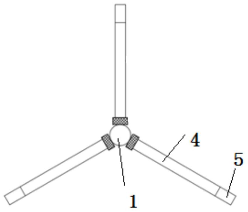
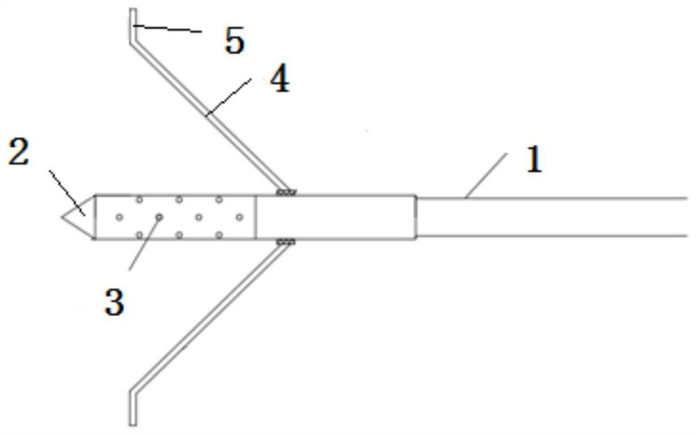
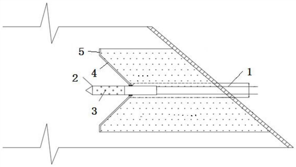
[0033] Such as Figure 1-5 As shown, a method for reinforcing the silty sand layer includes a stirring drill and a long anchor pipe 6. The drill bit part of the stirring drill includes a drill rod 1, and the drill rod 1 is provided with a cement grout For the liquid injection chamber that enters and exits, one end of the drill pipe 1 is provided with a drill bit 2 and the other end is provided with a grouting hole. The drill bit 2 is provided with at least two grouting holes 3 connected to the liquid injection chamber.

[0034] The side wall of the drill pipe 1 is provided with a stirring blade 4, and the other end of the stirring blade 4 is provided with a trigger protrusion 5. When the trigger protrusion 5 is subjected to the resistance directed from the drill bit 2 to the drill pipe 1, the stirring blade 4...


PUM


Abstract

The present invention proposes a kind of method that is used for reinforcing muddy sand layer, and its steps are as follows: S1: the drill bit part of stirring drilling rig drills toward the muddy sand layer direction, and in drilling process, stirring blade opens and The silty sand layer is stirred, and at the same time, the grouting equipment sprays the cement slurry into the silty sand layer through the grout hole, the liquid injection cavity of the drill pipe, and the grouting hole, so that the cement slurry and the silty sand layer are mixed and condensed into cement. Reinforced body; S2: The drill bit part withdraws from the silty sand layer. During the withdrawal process, the stirring blade is retracted, and at the same time, the cement slurry provided by the grouting equipment is sprayed into the hole drilled by the bit part through the grouting hole and sealed. ; S3: Move the mixing rig to the next position to be reinforced, repeat steps S1-S2; S4: Drill a re-reinforcement hole on the cement reinforcement, and insert the long anchor pipe into the re-reinforcement hole; S5: Provided by the grouting equipment The cement grout is injected into the re-reinforcement hole through the long anchor pipe, and penetrates into the gap of the cement reinforcement.

Description

technical field [0001] The invention relates to the field of civil engineering, in particular to a method for reinforcing muddy sand layers. Background technique [0002] The silty sandy soil layer is a unique soil structure in the coastal beach landform area. It is difficult and risky to carry out building construction on this foundation. Because the groundwater in the site area is rich and the upper rock layer and soil layer have strong water permeability, the groundwater in the site area and the soil layer are relatively strong. Sea water has a certain connection with water conservancy. During the excavation of the foundation pit, mud gushing, local collapse, and quicksand often occur, which not only greatly increases the safety risk of foundation pit excavation and the risk of slope instability, but also It also has a huge impact on the development speed of the project. Therefore, the reinforcement of the silty sand layer is a very important measure before the excavation...

Claims


Application Information

Patent Timeline
Patent Type & Authority Patents(China)
IPC IPC(8): E02D3/12E02D5/76C04B28/26
CPCE02D3/126E02D5/76C04B28/26C04B7/02C04B22/002C04B18/049
Inventor 邵文杰陈文尹王克义隗志远吕洪礼刘帅
Owner CHINA TIESIJU CIVIL ENG GRP CO LTD
Why Eureka
Try Eureka