
Ultralow-energy-consumption smoke combustion type waste incineration method

A technology of waste incineration and energy consumption, which is applied in the direction of combustion method, combustion type, combustion equipment, etc., can solve the problems of unsatisfactory water mist purification effect, unsatisfactory smoke and dust removal effect, and smoke and dust purification can not meet environmental protection requirements. Simple, improve the efficiency of the furnace, and thoroughly purify the smoke and dust

Pending Publication Date: 2021-04-30
姚舜
View PDF0 Cites 0 Cited by
  • Summary
  • Abstract
  • Description
  • Claims
  • Application Information

AI Technical Summary

Problems solved by technology

[0003] At present, high-voltage electrostatic adsorption, water mist spraying, and secondary combustion are generally used for gas purification, especially for dust purification. Although the purification effect of high-voltage electrostatic adsorption is better, it needs to be cleaned and replaced continuously. The effect of water mist purification is not ideal. The more advanced method of secondary combustion is to put clean fuel into the secondary combustion chamber, and rely on the high temperature generated by the combustion of clean fuel to eliminate smoke and dust. However, the effect of eliminating smoke and dust in this way is not ideal, and the purification of smoke and dust cannot meet environmental protection requirements.

Method used


Image

  • Ultralow-energy-consumption smoke combustion type waste incineration method
  • Ultralow-energy-consumption smoke combustion type waste incineration method
  • Ultralow-energy-consumption smoke combustion type waste incineration method

Examples


Embodiment Construction

[0015] The present invention is further described below in conjunction with accompanying drawing:

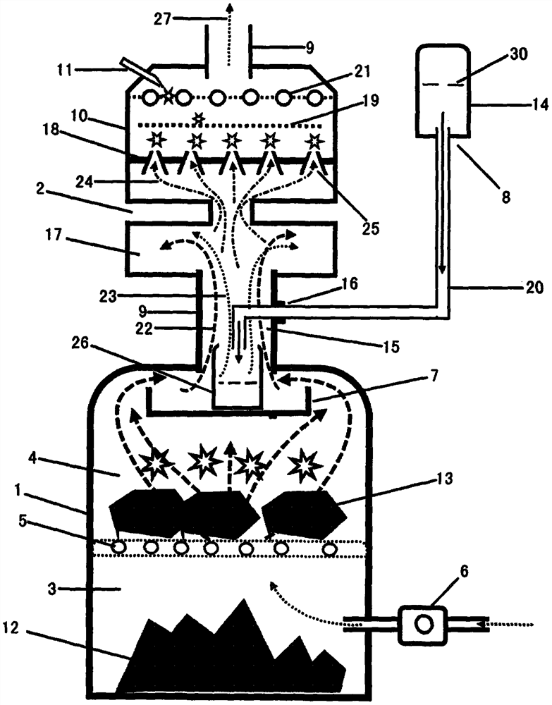
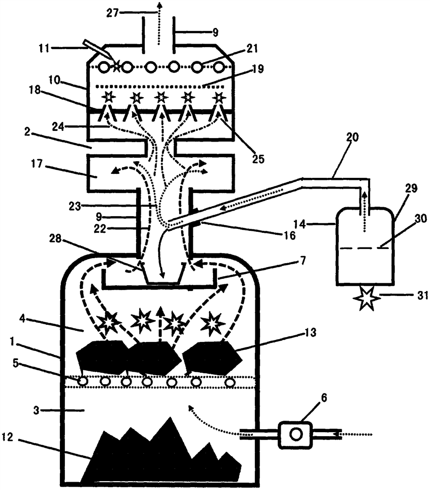
[0016] figure 1 Among them, the clean fuel vaporization supply device 15 is that there is a clean liquid fuel 30 in the external clean liquid fuel bottle 14, and the clean liquid fuel 30 enters the smoke pipe 9 from the clean fuel inlet 16 through the delivery pipe 20, and the clean liquid fuel 30 drops into it. The fuel vaporization plate 26 arranged below, the fuel vaporization plate 26 vaporizes the clean liquid fuel 30 under high temperature into vaporized clean fuel 23, the vaporized clean fuel 23 runs upwards and enters the mixing chamber 17, and the vaporized clean fuel 23 and the soot 22 are mixed Combustible smoke 24 is fully mixed in the air chamber 17 and is ignited when it runs upwards. The clean liquid fuel 30 is mainly an alcohol-based fuel, such as a fuel mainly composed of methanol, ethanol, and butanol.

[0017] figure 2 Among them, the clean fuel vaporizati...


PUM


Abstract

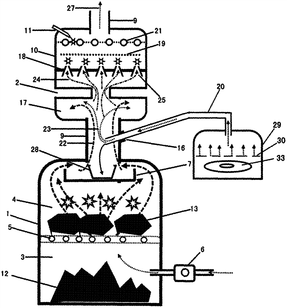
The invention discloses an ultralow-energy-consumption smoke combustion type waste incineration method, and belongs to the field of gas purification. At present, in a method with secondary combustion being quite advanced, clean fuel is put into a secondary combustion chamber, smoke dust is eliminated through high temperature generated by combustion of the clean fuel, but the smoke dust eliminating effect of the manner cannot meet the environmental protection requirement. By aiming at the revolutionary breakthrough of the prior art, the clean fuel is vaporized and mixed with the smoke dust, that is, the vaporized clean fuel is used for fully wrapping particles such as PM2.5 in the smoke dust to form combustible particles and combustible smoke dust, and then the combustible particles and the combustible smoke dust are burnt out. Smoke dust coming from a primary combustion chamber upwards enters a gas mixing chamber through a smoke pipe, the vaporized clean fuel also upwards enters the gas mixing chamber, the smoke dust and the vaporized clean fuel in the gas mixing chamber are fully mixed into combustible smoke dust under the action of gas rotational flow, and the aim of thoroughly purifying the smoke dust can be achieved by igniting the combustible smoke dust. By adopting the method, smoke dust is purified thoroughly, the structure is simple, maintenance is avoided, particularly, the smoke dust serves as fuel to be utilized, and the furnace combustion efficiency is greatly improved.

Description

[0001] Field [0002] The technology belongs to the field of gas purification, and in particular relates to an ultra-low energy consumption smoke-burning garbage incineration method. Background technique [0003] At present, high-voltage electrostatic adsorption, water mist spraying, and secondary combustion are generally used for gas purification, especially for dust purification. Although the purification effect of high-voltage electrostatic adsorption is better, it needs to be cleaned and replaced continuously. The effect of water mist purification is not ideal. The more advanced method of secondary combustion is to put clean fuel into the secondary combustion chamber, and rely on the high temperature generated by clean fuel combustion to eliminate smoke and dust. However, the effect of eliminating smoke and dust in this way is not ideal, and the purification of smoke and dust cannot meet environmental protection requirements. Contents of the invention [0004] The presen...

Claims


Application Information

Patent Timeline
Patent Type & Authority Applications(China)
IPC IPC(8): F23G5/00F23G5/44F23G7/06F23K5/00
CPCF23G5/00F23G5/44F23G7/06F23K5/002
Inventor 姚舜姚志勇姚志强
Owner 姚舜
Learn More