
Fireproof electric floor heating structure

A technology of electric floor heating and fireproof layer, applied in the field of floor heating, can solve the problems of complicated installation process of electric floor heating, affecting user experience, uneven heating effect, etc., achieving the effect of simple installation, easy installation and disassembly, and improved efficiency

Pending Publication Date: 2021-04-30
王晶
View PDF6 Cites 0 Cited by
  • Summary
  • Abstract
  • Description
  • Claims
  • Application Information

AI Technical Summary

Problems solved by technology

[0002] At present, a large part of the total energy consumption of the society is used in the construction field, from the currently widely used building decoration materials such as exterior wall panels, interior wall panels, floors, suspended ceilings, equipment such as air conditioners, floor heating, ground source heat, boiler water heaters, etc. , There are problems in different situations. The purpose of people using heating or air conditioning is to balance the indoor air temperature and increase indoor comfort. Floor heating is the abbreviation of ground radiation heating. The heat medium evenly heats the entire ground, and uses the heat storage of the ground itself and the law of upward radiation to conduct heat from bottom to top to achieve the purpose of heating. Compared with traditional heating methods, floor heating is more in line with the law of heat conduction and is more conducive to aesthetics , more scientific, more energy-saving, electric floor heating is to bury the heating cable or electric heating film in the floor as a heat source to heat the floor, and use a thermostat to control the room temperature or floor temperature to realize the heating method of ground radiant heating, which can solve the problem of water supply and Heating in places where the heating source is limited, but in the existing electric floor heating structure, there are often many problems, such as the installation process of electric floor heating is complicated, it is not easy to maintain, and the fire performance is weak, and the current electric floor heating heat exchange structure is simple , the exchange efficiency is low, and it also causes the heating effect of the whole room to be uneven, thus affecting the user experience

Method used


Image

  • Fireproof electric floor heating structure
  • Fireproof electric floor heating structure
  • Fireproof electric floor heating structure

Examples


Embodiment approach

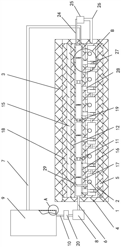
[0029] As a specific embodiment of the present invention, the first number column 28 is located at one end of the adjacent impeller 32 close to the water storage tank 9, and the first number column 28 is used to push the water in the water storage tank 11 to the impeller 32; When the first column 28 is farther away from the fan 25 than the adjacent impeller 32, when the first column 28 hits the water storage tank 11, the water flow in the water storage tank 11 will quickly impact the impeller 32, thereby further increasing the rotation speed of the impeller 32. , and then increase the rotation speed of No. 2 fan blade 31; the faster rotation of No. 2 fan blade 31 improves the moving speed of gas, thereby reducing the workload of fan 25 and indirectly increasing the rotation speed of No. 1 fan blade 27 , and then make the No. 1 pillar 28 hit the water storage tank 11 more violently.

[0030] As a specific embodiment of the present invention, the bottom end of the floor 3 is pro...


PUM


Abstract

The invention belongs to the technical field of floor heating, in particular to a fireproof electric floor heating structure. The fireproof electric floor heating structure comprises a plurality of electric heating pipes, a plurality of heating boxes, a fireproof layer, a floor, an installation layer, a heat insulation plate, a water storage layer, a water inlet pipe, a water outlet pipe, a water suction pump, a water storage tank and a water passing pipe, an installation cavity is arranged in the installation layer, the bottom end of the heat insulation plate is connected with the lower wall of the installation cavity, heating cavities are formed in the plurality of heating boxes correspondingly, the plurality of electric heating pipes are located in the plurality of heating cavities correspondingly, the bottom ends of the plurality of heating boxes are connected with the top end of the heat insulation plate, the top ends of the plurality of heating boxes are connected with the bottom end of the water storage layer, the water storage layer comprises a plurality of water storage tanks, and the plurality of water storage tanks communicate with one another. According to the fireproof electric floor heating structure, the fireproof plate is composed of a plurality of fireproof plate bodies, connecting buckles and connecting seats, so that the electric floor heating structure is convenient to install and dismount, the installation is simple, the maintenance is convenient, the heat exchange efficiency is high, and the heating effect is more uniform.

Description

technical field [0001] The invention relates to the technical field of floor heating, in particular to a fireproof electric floor heating structure. Background technique [0002] At present, a large part of the total energy consumption of the society is used in the construction field, from the large-scale application of building decoration materials such as exterior wall panels, interior wall panels, floors, ceilings, equipment such as air conditioners, floor heating, ground source heat, boiler water heaters, etc. , There are problems in different situations. The purpose of people using heating or air conditioning is to balance the indoor air temperature and increase indoor comfort. Floor heating is the abbreviation of ground radiation heating. The heat medium evenly heats the entire ground, and uses the heat storage of the ground itself and the law of upward radiation to conduct heat from bottom to top to achieve the purpose of heating. Compared with traditional heating met...

Claims


Application Information

Patent Timeline
Patent Type & Authority Applications(China)
IPC IPC(8): F24D13/02F24D13/04F24D19/00F24D19/10
CPCF24D13/024F24D13/04F24D19/008F24D19/1096
Inventor 王晶朱文艳
Owner 王晶
Learn More