Dental implant embedding tool

A technology for dental implants and tooling, applied in dental prosthesis, dentistry, measuring devices, etc., can solve problems such as high labor intensity, high scrap rate, skew, etc., and achieve improved efficiency and accuracy, good balance and stability , the effect of easy connection

Active Publication Date: 2021-04-30
山东省医疗器械产品质量检验中心
View PDF5 Cites 0 Cited by
  • Summary
  • Abstract
  • Description
  • Claims
  • Application Information

AI Technical Summary

Problems solved by technology

[0006] 1. When carrying out the fatigue strength test, there are often many batches of products. When the operator inserts the dental implant into the liquid alloy, the liquid alloy has been solidifying as time goes by, so there will be some cracks in the sleeve. The situation where the liquid alloy solidifies before the corresponding dental implant is inserted, causing the dental implant to be inserted too late;
[0007] 2. The current embedding process needs to manually maintain the verticality of the dental implant and the height of the dental implant protruding from the liquid alloy liquid level, which will cause relatively large errors, and the verticality and height are not guaranteed, which affects the test. the accuracy of the results;
[0008] 3. The efficiency of manual operation is very low, because the liquid alloy in the critical state of solidification has a high viscosity and a certain hardness. It will be laborious and labor-intensive to insert the dental implant into the liquid alloy. If there is skew, it is difficult to adjust, and the rejection rate is relatively high

Method used


Image

  • Dental implant embedding tool
  • Dental implant embedding tool
  • Dental implant embedding tool

Examples


Embodiment 1

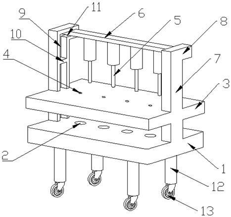
[0047] Such as figure 1 As shown, this embodiment provides a dental implant embedding tool, including a base plate 1, a placement groove 2 for accommodating a sleeve is provided on the base plate 1, a top plate 3 is provided above the bottom plate 1, and the top plate 3 is parallel to the bottom plate 1 and the top plate 3 and the bottom plate 1 are connected by a connecting frame; the top plate 3 is provided with a guide hole 4 for dental implants to pass through, and the guide hole 4 corresponds to the placement groove 2 And the axis of the guide hole 4 is perpendicular to the bottom surface of the placement groove 2; the top of the top plate 3 is provided with a lower pressing rod 5, and the lower pressing rod 5 corresponds to the guide hole 4 and can be inserted from the guide hole 4. Through it, the lower pressing rod 5 can move up and down and a limiting device is arranged on the track where it moves up and down.

[0048] In order to improve embedding efficiency and sav...

Embodiment 2

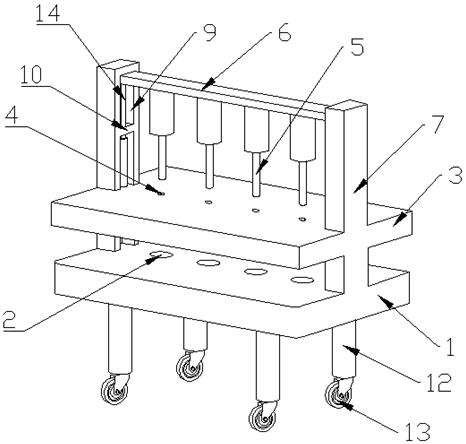
[0058] The features of this embodiment that are the same as those of Embodiment 1 will not be described in detail. The features of this embodiment that are different from Embodiment 1 are: figure 2 As shown, the present embodiment adopts an automatic driving mode to drive the connecting rod 6 and the lower pressing rod 5 to move, the connecting rod 6 is connected with a linear drive device 14, the output shaft of the linear drive device 14 is connected to the connecting rod 6 and can Drive described connecting rod 6 to move up and down.

[0059] Specifically, the linear drive device 14 may adopt linear motors, electric push rods, hydraulic cylinders, air cylinders and other devices that output linear motion.

[0060] In this embodiment, the main body of the driving device 14 is installed at the position below the limit block 10 in the track 9, and the output shaft of the drive device 14 passes through the limit block 10 and is connected to the connecting rod 6, so that it can...

Embodiment 3

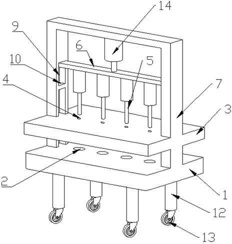
[0064] The same features of this embodiment and Embodiment 2 will not be described in detail. The different features of this embodiment and Embodiment 2 are: image 3 As shown, the bracket 7 of this embodiment forms the shape of a gantry, and the driving device 14 is arranged on the beam of the gantry to realize the driving of the connecting rod 6 and the pressing rod 5 .

[0065] The working principle of this embodiment is the same as that of the second embodiment.


PUM


Abstract

The invention discloses a dental implant embedding tool, which belongs to the technical field of medical instrument inspection, and structurally comprises a bottom plate, a placing groove for accommodating a sleeve is formed in the bottom plate, a top plate is arranged above the bottom plate, the top plate is parallel to the bottom plate, and the top plate and the bottom plate are connected through a connecting frame. A guide hole through which the dental implant passes is formed in the top plate, the guide hole corresponds to the placement groove, and the axis of the guide hole is perpendicular to the bottom surface of the placement groove; a lower pressing rod is arranged above the top plate, corresponds to the guide hole and can penetrate through the guide hole, the lower pressing rod can move up and down, and a limiting device is arranged on a rail where the lower pressing rod moves up and down. The technical scheme provided by the embodiment of the invention is suitable for embedding the dental implant in a fatigue test, the embedding efficiency can be improved, the manpower can be saved, and the verticality and the height accuracy of extending out of the liquid level of the liquid alloy can be ensured.

Description

technical field [0001] The invention relates to the technical field of medical device inspection, in particular to a dental implant embedding tool, which is especially suitable for the test of the fatigue strength of the dental implant. Background technique [0002] Dental implants, also known as artificial tooth roots, are surgically implanted into the upper and lower jaws of the missing teeth of the human body. After the surgical wound heals, a device for repairing dentures is installed on its upper part. Dental implants are in direct contact with human tissues in clinical use. In order to ensure people's life, health and safety, medical devices acting on the human body must pass strict quality inspections before they can be put into use. Among them, fatigue strength is an important indicator of dental implants. [0003] The structure of the dental implant is a small cylinder, and its outer surface is provided with external threads. When performing a fatigue strength test,...

Claims


Application Information

Patent Timeline
Patent Type & Authority Applications(China)
IPC IPC(8): G01N1/36G01N3/32A61C13/00
CPCG01N1/36G01N3/32A61C13/0003G01N2001/368G01N2203/0073G01N2203/0298
Inventor 王凯刘万宗梁金奎陈洪建郭士玉
Owner 山东省医疗器械产品质量检验中心
Why Eureka
Try Eureka