Supercharge Your Innovation With Domain-Expert AI Agents!

Slow-wave multi-path power divider chip of Ka waveband

A power divider and ka-band technology, which is applied in the field of slow-wave multi-channel power divider chips, can solve the problems of inconvenient miniaturization design and large chip area

Active Publication Date: 2021-04-30
成都天成电科科技有限公司
View PDF5 Cites 0 Cited by
  • Summary
  • Abstract
  • Description
  • Claims
  • Application Information

AI Technical Summary

Problems solved by technology

[0004] In view of this, the purpose of the present invention is to overcome the deficiencies in the prior art, and provide a slow-wave multi-channel power divider chip in the Ka band, to solve the problem that the length of the 1 / 4 wavelength line used in the prior art causes the entire chip area to be relatively large. Large, inconvenient design issues for miniaturization

Method used


Image

  • Slow-wave multi-path power divider chip of Ka waveband
  • Slow-wave multi-path power divider chip of Ka waveband
  • Slow-wave multi-path power divider chip of Ka waveband

Examples


Embodiment Construction

[0032] In order to make the purpose, technical solution and advantages of the present invention clearer, the technical solution of the present invention will be described in detail below. Apparently, the described embodiments are only some of the embodiments of the present invention, but not all of them. Based on the embodiments of the present invention, all other implementations obtained by persons of ordinary skill in the art without making creative efforts fall within the protection scope of the present invention.

[0033] A specific Ka-band slow-wave multiplexer chip provided in the embodiment of the present application will be described below with reference to the accompanying drawings.

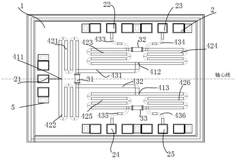
[0034] Such as figure 1 As shown, the Ka-band slow-wave multi-channel power divider chip provided in the embodiment of the present application includes a GaAs substrate 1, and a power dividing circuit is arranged on the GaAs substrate 1; the power dividing circuit includes: a first circ...


PUM

PropertyMeasurementUnit
Widthaaaaaaaaaa
Characteristic impedanceaaaaaaaaaa
Widthaaaaaaaaaa

Abstract

The invention relates to a slow-wave multi-path power divider chip of a Ka waveband. The slow-wave multi-path power divider chip comprises a power dividing circuit. The power dividing circuit comprises a first circuit, a second circuit, a third circuit and a fourth circuit. The first circuit and the third circuit, and the second circuit and the third circuit are symmetrically arranged by taking a first T-shaped switching microstrip line as a symmetric axis; and a third slow-wave microstrip line and a fourth slow-wave microstrip line are symmetrically arranged by taking a second T-shaped switching microstrip line as a symmetric axis, and a fifth slow-wave microstrip line and a sixth slow-wave microstrip line are symmetrically arranged by taking a third T-shaped switching microstrip line as a symmetric axis. A slow-wave microstrip line structure is adopted to replace a quarter-wavelength microstrip line of a traditional power divider, the chip technology is combined, the physical length of the slow-wave microstrip line is about one eighth of the physical length of the traditional quarter-wavelength microstrip line, and on the premise that various indexes of a power divider chip are achieved, the area of the power divider chip is reduced to less than one fifth of the area of a traditional power divider chip.

Description

technical field [0001] The invention belongs to the technical field of radio frequency chips, and in particular relates to a Ka-band slow-wave multi-channel power divider chip. Background technique [0002] Miniaturized power divider chips are widely used in microwave communication, radar, electronic countermeasures and other fields. The power divider can divide one input signal into two or multiple energy equal or unequal output signals. The current power divider can be mainly divided into three forms: air board line network form, microstrip network form and waveguide form . The waveguide form and the air board line network form have high power capacity, but the volume and weight are relatively large, which is not conducive to miniaturization and integration. The power splitter in the form of a microstrip network has become the focus of miniaturization research. The traditional Wilkinson power splitter needs to occupy a larger layout due to the two transmission lines with...

Claims


Application Information

Patent Timeline
IPC IPC(8): H01P5/16
CPCH01P5/16
Inventor 方勇刘强于磊
Owner 成都天成电科科技有限公司
Features
  • R&D
  • Intellectual Property
  • Life Sciences
  • Materials
  • Tech Scout
  • Unparalleled Data Quality
  • Higher Quality Content
  • 60% Fewer Hallucinations
Learn More