Anti-pollution storage equipment for clinical laboratory
A storage device, anti-pollution technology, applied in the field of medical equipment
- Summary
- Abstract
- Description
- Claims
- Application Information
AI Technical Summary
Problems solved by technology
Method used
Image
Examples
Embodiment 1
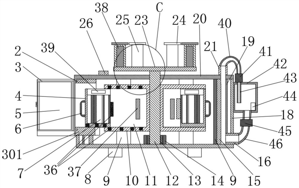
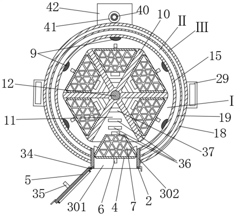
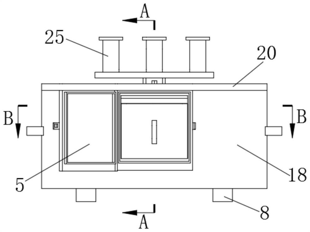
[0053] Such as Figure 1 to Figure 9 As shown, the anti-pollution storage device of the present invention includes at least a rack 10 and a housing 18 . The storage rack 10 is polygonal and is arranged in the cavity of the housing 18 in a manner that the rotation angle can be adjusted, so that when one of the end faces of the storage rack 10 coincides with the outlet of the housing 18 , at least one sample storage box 4 disposed in the sample storage tank of the rack 10 is moved out of the housing 18 . Specifically, the storage rack 10 is a three-dimensional structure with hexagons, octagons or more sides. The rack 10 is rotatably mounted inside the casing 18 . Preferably, the housing 18 is in the shape of a hollow cylinder with one end open, which facilitates the assembly of the device. Preferably, the first end of the housing 18 is provided with a cover 20 . The inner surface of the second end of the housing 18 is provided with a fixing block 14 . Preferably, the cover ...
Embodiment 2
[0075] Such as Figure 10 to Figure 14 As shown, the anti-pollution storage device for laboratories of the present invention at least includes a housing 18 and a shelf 10 . The housing 18 is hollow. Preferably, the housing 18 is in the shape of a hollow cylinder with one end open. Preferably, the first end of the housing 18 is open. Easy to assemble the equipment. Preferably, the first end of the housing 18 is provided with a cover 20 . The inner surface of the second end of the housing 18 is provided with a fixing block 14 . Preferably, the cover 20 can be fixed on the housing 18 by bolts, which is convenient for disassembly. The fixing block 14 is welded on the inner side of the second end of the housing 18 . The rack 10 is disposed inside the housing 18 , wherein: the housing 18 is provided with a rotating shaft 12 . The rack 10 is installed on the rotating shaft 12 . The first end of the shaft 12 is mounted on the fixed block 14 . Preferably, a bearing 13 is insta...
Embodiment 3
[0085] The power supply 38 is electrically connected to a voltage regulation module 57 . Both the speed sensor 56 and the voltage regulation module 57 are communicatively coupled to the data processing unit 54 . Preferably, the voltage regulation module 57 may be an intelligent voltage stepless regulation device, and is electrically connected to the power supply 38 . For example, when the sample storage box 4 is subjected to the repulsive force, because it is in a suspended state in the horizontal direction, the sample storage box 4 moves under the action of the repulsive force, and the repulsive force is continuously reduced in the process of gradually moving away from the electromagnet 37, so the sample storage box The box 4 is in an accelerated motion state in which the acceleration decreases during the moving process. Since the samples are basically collected in glass containers such as test tubes, excessive vibration may cause damage to the test tubes at too high a speed...
PUM
 Abstract
Description
Claims
Application Information
 - R&D
- Intellectual Property
- Life Sciences
- Materials
- Tech Scout
- Unparalleled Data Quality
- Higher Quality Content
- 60% Fewer Hallucinations
Browse by: Latest US Patents, China's latest patents, Technical Efficacy Thesaurus, Application Domain, Technology Topic, Popular Technical Reports.
© 2025 PatSnap. All rights reserved.Legal|Privacy policy|Modern Slavery Act Transparency Statement|Sitemap|About US| Contact US: help@patsnap.com


