Adhesive film cutting device for wafer

A technology for cutting equipment and wafers, which is applied to the cleaning method of tools, cleaning methods and utensils, metal processing, etc., and can solve the problems of inconsistent wafer surface size, inability to use the wafer surface normally, and the edge of the adhesive film Wrinkle and other problems, to achieve the effect of reducing sticking to the outer wall of the rotating ring and reducing the adsorption force as the rotating ring rotates

Inactive Publication Date: 2021-05-07
李岁敏
View PDF0 Cites 0 Cited by
  • Summary
  • Abstract
  • Description
  • Claims
  • Application Information

AI Technical Summary

Problems solved by technology

[0002] After the wafer processing is completed, the product is covered with an adhesive film, which is beneficial to the protection of the wafer and reduces the phenomenon of scratches on the product surface during transportation. The adhesive film is cut into the same size as the product by a cutting machine. The film is placed horizontally on the cutting table of the cutting machine, the gantry and the sliding block move together to drive the cutter to move, and the laser of the cutter is irradiated on the surface of the film, so that the film is hot-melted and cut off; in the prior art, the film is cut by cutting machine When cutting, because the gantry moves on the top of the cutting table to drive the surrounding air flow, and the film is light in weight, when the gantry moves, the film on the edge of the cutting table will float up due to the air flow, and the edge of the film will be wrinkled. Phenomenon, when the adhesive film is cut, the shape of the adhesive film changes, which does not match the surface size of the wafer, and cannot be used to cover the surface of the wafer normally.

Method used


Image

  • Adhesive film cutting device for wafer
  • Adhesive film cutting device for wafer
  • Adhesive film cutting device for wafer

Examples


Embodiment 1

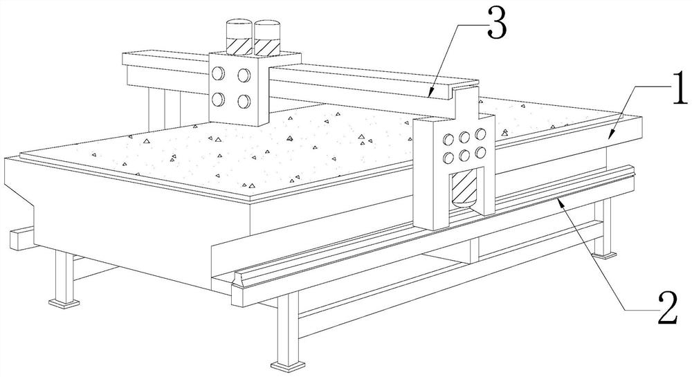
[0027] as attached figure 1 To attach Figure 5 Shown:

[0028] The present invention provides a film cutting device for wafers. Its structure includes a body 1, a slider 2, and a gantry 3. The slider 2 is horizontally installed in the middle of both sides of the body 1. The gantry 3 is located at Above the body 1, and in cooperation with the slide block 2.

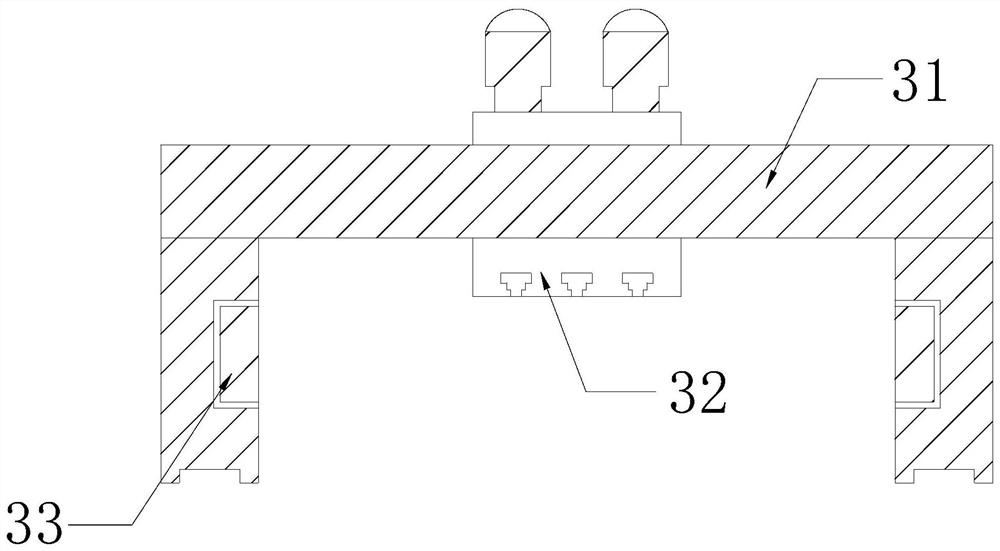
[0029] Described gantry frame 3 is provided with support frame 31, cutter 32, limit mechanism 33, and described support frame 31 is positioned at the outside of gantry frame 3, and described cutter 32 is vertically installed on support frame 31 top center position, and described limiter The mechanism 33 is nested inside the middle part of the support frame 31 .

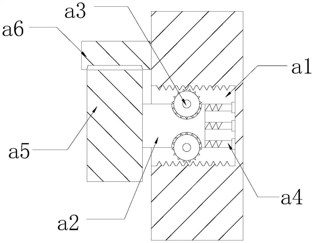
[0030] Wherein, the limit mechanism 33 is provided with a matching groove a1, a support rod a2, a gear a3, a telescopic rod a4, a rotating ring a5, and a matching block a6. The right end of the support rod a2 is sleeved inside the matching groove a1, the gear...

Embodiment 2

[0036] as attached Image 6 To attach Figure 8 Shown:

[0037]Wherein, the matching block a6 is provided with an expansion rod e1, an active groove e2, an air cavity e3, a push plate e4, and a limit rod e5, and the expansion rod e1 is installed on the right side of the matching block a6, and the active groove e2 is arranged on In the middle of the bottom surface of the matching block a6, the air cavity e3 is set inside the matching block a6 and above the movable groove e2, the push plate e4 is set inside the bottom of the air cavity e3, and the limit rod e5 is installed on the push plate e4 Between the tops of both ends and the inner wall of the air cavity e3, the top of the push plate e4 has an uneven surface, which can increase the force-bearing area of ​​the top of the push plate e4 and speed up the airflow inside the air cavity e3 when the push plate e4 moves up. Promote diffusion, the expansion rod e1 is provided with two, and is at the same horizontal angle, which is ...


PUM


Abstract

The invention discloses an adhesive film cutting device for a wafer. The adhesive film cutting device for the wafer structurally comprises a machine body, sliding blocks and a portal frame. Considering the problem that since the portal frame moves on the top of a cutting table and drives surrounding airflow to flow, the edge of an adhesive film is prone to floating upwards under the action of the airflow, a rotating ring in a limiting mechanism makes contact with the surface of the edge of the adhesive film along with movement of the portal frame, the rotating ring presses downwards and smooths the edge of the adhesive film, the phenomenon that the adhesive film on the edge of the cutting table floats upwards under the action of airflow is reduced, the phenomenon that the edge of the adhesive film is wrinkled is reduced, the cut shape of the adhesive film keeps unchanged beneficially, the adhesive film is matched with the surface size of a wafer, and the adhesive film can be normally used for covering the surface of the wafer. Considering the problem that since adhesive film fluid is attached to the outer wall of the rotating ring, the phenomenon that the adhesive film rotates along with the rotating ring under the action of adsorption force of the fluid is prone to happen, the adhesive film fluid on the outer wall of the rotating ring is removed through a scraping plate in a matching block, so that the outer wall of the rotating ring can be kept clean.

Description

technical field [0001] The invention belongs to the field of wafer coating, and more specifically relates to an adhesive film cutting device for wafers. Background technique [0002] After the wafer processing is completed, the product is covered with an adhesive film, which is beneficial to the protection of the wafer and reduces the phenomenon of scratches on the product surface during transportation. The adhesive film is cut into the same size as the product by a cutting machine. The film is placed horizontally on the cutting table of the cutting machine, the gantry and the sliding block move together to drive the cutter to move, and the laser of the cutter is irradiated on the surface of the film, so that the film is hot-melted and cut off; in the prior art, the film is cut by cutting machine When cutting, because the gantry moves on the top of the cutting table to drive the surrounding air flow, and the film is light in weight, when the gantry moves, the film on the edg...

Claims


Application Information

Patent Timeline
Patent Type & Authority Applications(China)
IPC IPC(8): B29C63/02B08B1/00B08B13/00B26D1/10B26D7/26
CPCB08B1/001B08B13/00B26D1/10B26D7/2628B29C63/02
Inventor 郑月英
Owner 李岁敏
Why Eureka
Try Eureka