
Marker selection method for oil field logging

A marker and well logging technology, which is applied in the directions of measurement, earthwork drilling, wellbore/well components, etc., can solve the problems of crawler resistance, casing deformation, manpower, and high replacement cost

Pending Publication Date: 2021-05-07
四川松云科技有限公司
View PDF0 Cites 1 Cited by
  • Summary
  • Abstract
  • Description
  • Claims
  • Application Information

AI Technical Summary

Problems solved by technology

[0004] Traditional instruments go downhole by their own gravity, and it is difficult for the instrument string to continue moving after reaching the vicinity of the deflection; for this reason, Schlumberger specially designed the MaxTRAC crawler, which drags the signal cable and power cable, and carries the instrument The string enters the horizontal section; but once the horizontal section is relatively long, or the wellbore trajectory is tortuous and undulating, or there is casing deformation, it is easy to cause the crawler to be blocked, or even get stuck in the horizontal section, causing accidents;
[0005] 2) Problems with production testing
[0006] Traditional instruments go downhole with cables. Due to the existence of instruments and cables, it is necessary to use unconventional methods such as gas lift to lift the production liquid to the surface, causing the liquid to flow, thereby measuring parameters; these measures have objectively changed the entire horizontal section. The flow environment is easy to cause deviations between the test data and the real data in normal production, resulting in inaccurate test conclusions;
[0007] 3) Adaptation to harsh underground conditions
With this method, when replacing ordinary markers, well shutdown operations are required, which affects the normal operation of the oil well, and the cost of manpower and replacement is high

Method used


Image

  • Marker selection method for oil field logging
  • Marker selection method for oil field logging
  • Marker selection method for oil field logging

Examples


Embodiment 1

[0097] The general procedure for testing the fluid production profile of a horizontal oil well is as follows.

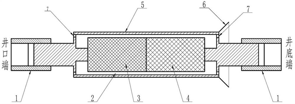
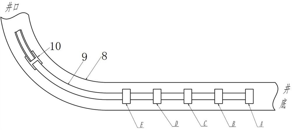
[0098] 1) Design of downhole release device deployment plan: determine which downhole fluid production conditions should be paid attention to according to well conditions, and count the number of layers and the specific positions of the front and rear ends of each layer (near the bottom of the well is the front end, and away from the bottom of the well for the backend). A release device is to be deployed at the back end of each concerned interval, and the number of concerned intervals is the number of release devices that need to be deployed. Such as figure 2 As shown, for example, it is necessary to measure 5 intervals, and it is necessary to deploy 5 release devices to the back end of each interval.

[0099] 2) Factory production: According to the above, it is necessary to measure the liquid production of 5 layers, first form 5 kinds of solid oil-based markers a...

Embodiment 2

[0109] Example 2 Water-seeking test for high water-cut level oil wells

[0110] For high water-cut wells, if there is still a small amount of oil production, it is necessary not only to find out the main water-production interval, but also to find the oil-production interval. The traditional water-seeking test method mainly focuses on the main water-producing layer, but in reality, if the main water-producing layer is accompanied by a small amount of oil production, then the main water-producing layer is blocked according to the test conclusion, and the result may be water plugging It stopped, and a small amount of oil was also blocked. Therefore, if the main oil-producing section of the well can be given at the same time as the main water-producing section, it will provide more comprehensive basic data for the subsequent comprehensive management.

[0111] Such as figure 2 As shown, for a high water-cut horizontal well with 5 intervals, it is planned to deploy 5 release dev...

Embodiment 3

[0116] Example 3 Full life cycle production monitoring of horizontal wells

[0117] For horizontal oil wells, the technology of this patent application can be used to implement the production monitoring of the entire life cycle, that is, to monitor the liquid production of each section of the horizontal well, including the flow rate of each section, the ratio of oil to water, and as the production progresses, the production layer trend of change. Mastering this information at any time will provide complete basic data for the scientific decision-making of production management and maintenance programs of horizontal wells.

[0118] Such as figure 2As shown, a horizontal well that has just been completed, or a horizontal well that has been in production for many years, has a total of 5 intervals. It is necessary to monitor the fluid production of each interval for a long time. At the back end of each interval ( A release device is deployed on the layer away from the bottom of ...


PUM


Abstract

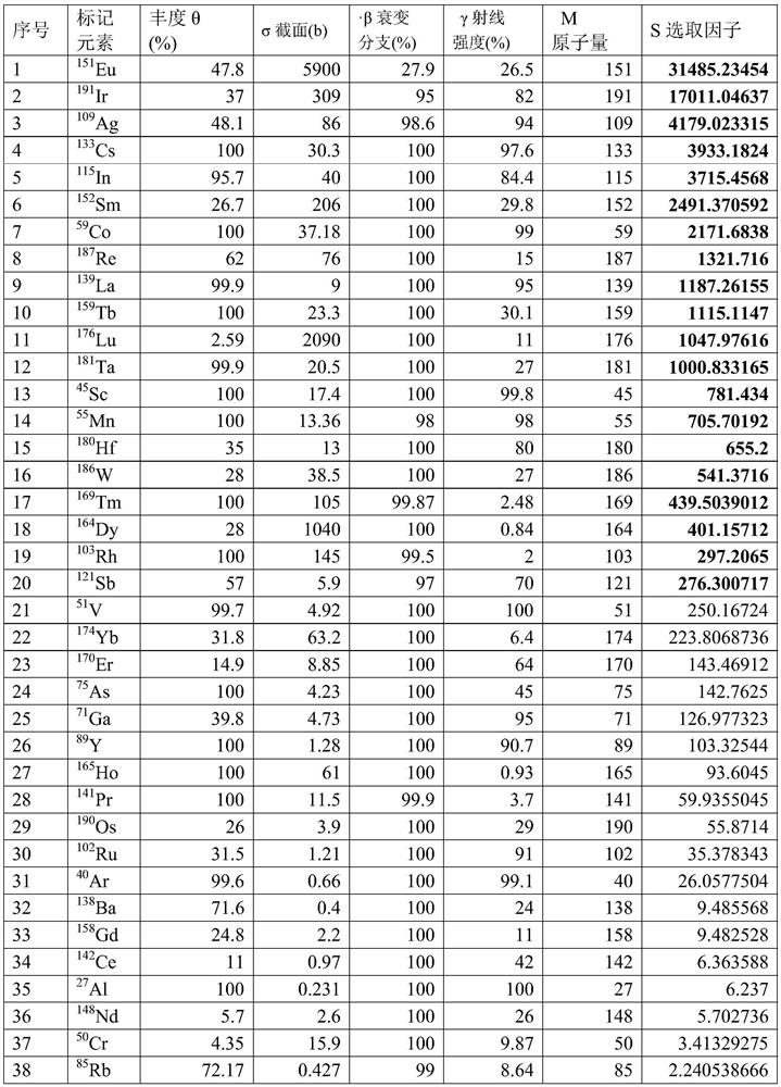
The invention discloses a marker selection method for oil field logging. The method comprises the following steps of (a) selecting elements capable of participating in neutron activation treatment, and calculating element factors S of the selected elements according to the following formula (1): S=[theta]*[sigma]*[beta]*[gamma] / M(1); and (b) sorting the elements in a sequence from large S factors to small S factors according to the determination result in the step a, and primarily selecting the elements which are sorted in the front; then performing gamma ray interference elimination in the primarily selected elements, i.e., only remaining the elements with the large S factors in the elements with the characteristic gamma ray signal mutual interference; and regarding the finally left elements as marked elements. The invention provides a brand-new marker selection method; and through cooperation with the trace analysis, the flow rate of produced liquid in each target position under a well and the proportion of water to crude oil in the produced liquid can be accurately reduced. Meanwhile, the normal operation state of a horizontal well cannot be damaged, system errors can be effectively reduced, and the accuracy and reliability of the measurement result are improved.

Description

technical field [0001] The invention relates to the field of oilfield exploitation, in particular to the field of underground measurement of oilfield exploitation, in particular to a method for selecting markers for oilfield well logging. This application provides a new method for selecting markers for oil field logging, which provides a new idea for the selection of markers. Based on the markers for oil field logging obtained by the selection method of this application, and the use of trace analysis, it is possible to accurately restore the ratio of water and crude oil in the fluid produced at each target location downhole. Background technique [0002] Fluid production profile testing of horizontal oil wells is a difficult problem in the field of petroleum logging, which involves the following aspects: [0003] 1) Accessibility problem [0004] Traditional instruments go downhole by their own gravity, and it is difficult for the instrument string to continue moving after...

Claims


Application Information

Patent Timeline
IPC IPC(8): E21B47/11E21B47/00E21B43/26
CPCE21B47/00E21B43/26
Inventor 刘建赵燕梅梅坚任丽容
Owner 四川松云科技有限公司
Learn More