Drainage device for open pit mine

A technology for drainage devices and open pit mines, applied in mining devices, drainage, pump devices, etc., can solve the problems of increasing the electric energy of centrifugal pumps, time-consuming and laborious, and increasing the load of centrifugal pumps, so as to avoid obstruction of drainage, reduce electric energy, and reduce The effect of the probability of failure

Inactive Publication Date: 2021-05-07
杰太
View PDF0 Cites 1 Cited by
  • Summary
  • Abstract
  • Description
  • Claims
  • Application Information

AI Technical Summary

Problems solved by technology

[0003] When the existing drainage device drains the water in the open-pit mine water tank, a large amount of impurities at the bottom of the filter screen will accumulate. When the accumulation is too much, manual cleaning is often required, which is time-consuming and laborious. Moreover, the accumulation of impurities will not only increase the operating efficiency of the centrifugal pump. load, and will increase the power consumption of the centrifugal pump, in view of this, a drainage device for open-pit mines is now provided

Method used


Image

  • Drainage device for open pit mine
  • Drainage device for open pit mine
  • Drainage device for open pit mine

Examples


Embodiment 1

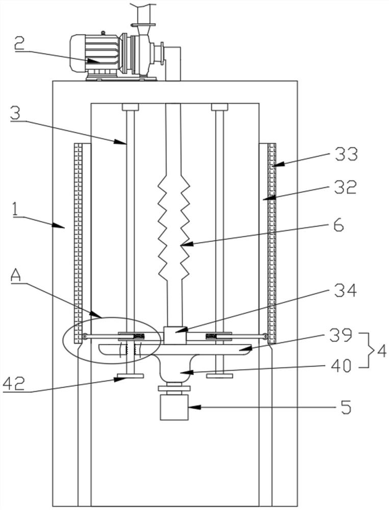
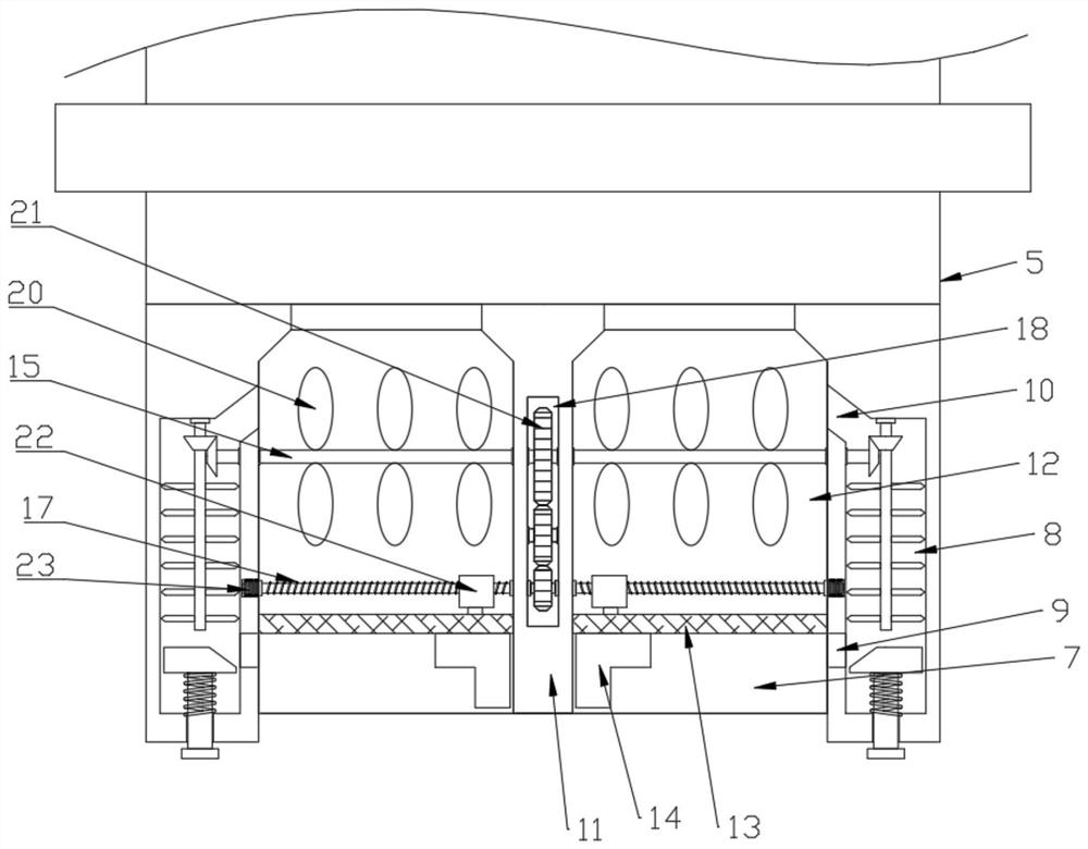
[0025] see Figure 1-5 , a drainage device for open-pit mines, including a mounting frame 1 installed in the open-pit mine water tank and a centrifugal pump 2 arranged on the mounting frame 1, the top surface of the inner wall of the mounting frame 1 is fixedly provided with two slide bars 3, A floating body 4 is movably installed on the slide bar 3, and the bottom of the floating body 4 is fixedly provided with a fixed box 5, and the top of the fixed box 5 is connected with the input end of the centrifugal pump 2 through a flexible hose 6, and the fixed box There is a groove 7 in the bottom end surface of the box 5, and the bottom end surface of the fixed box 5 is located on both sides of the groove 7, and a slag discharge groove 8 is symmetrically provided. The slag discharge port 9 and the connection port 10, and a crushing assembly is provided in the slag discharge tank 8, and a vertical partition 11 is fixed in the groove 7, and the groove 7 is divided into two by the par...

Embodiment 2

[0032] This embodiment expands the functions on the basis of Embodiment 1, specifically:

[0033] The inner surface of the installation frame 1 is symmetrically provided with a chute 32, the chute 32 is embedded with a conductive plate 33 connected in series with the centrifugal pump 2, and the top of the floating body 4 is provided with a conductive plate 33 for both sides. Electrically connected connection assembly, the connection assembly includes a sleeve block 34 and connection units arranged on both sides of the sleeve block 34, the sleeve block 34 is sleeved on the telescopic hose 6, and the sleeve block 34 is connected to the top surface of the floating body 4 Fixedly connected, the connecting unit includes a telescopic sleeve 35, a telescopic rod 36 and an induction roller 37, the telescopic sleeve 35 is fixedly connected with the cover block 34, and one end of the telescopic rod 36 is rotatably connected with an induction roller 37, and the telescopic rod The other e...


PUM


Abstract

The invention relates to the technical field of drainage devices, and particularly relates to a drainage device for an open pit mine. The drainage device comprises a mounting frame and a centrifugal pump, wherein a floating body is movably arranged in the mounting frame, a fixing box is fixedly arranged at the bottom of the floating body, the top of the fixing box is connected with the input end of the centrifugal pump through a telescopic hose, a groove and two slag discharging grooves are formed in the end face of the bottom of the fixing box, crushing assemblies are arranged in the slag discharging grooves, two water inlet grooves are formed in the groove, filter screens are fixedly arranged in the water inlet grooves, shifting blocks are arranged on the filter screens, and the shifting blocks are slidably connected to the bottom surfaces of the filter screens and are driven by a driving assembly. The driving assembly is arranged so that the automatic cleaning effect on the filter screens can be achieved, the drainage blockage caused by accumulation of a large number of impurities is avoided to a certain extent, the working efficiency of drainage is greatly improved, meanwhile, the load of the centrifugal pump is reduced, the probability of faults of the centrifugal pump is reduced, the electric energy consumed by the centrifugal pump is also reduced, and the device is more environment-friendly.

Description

technical field [0001] The invention relates to the technical field of drainage devices, in particular to a drainage device for open-pit mines. Background technique [0002] In the process of mining ore, groundwater and surface water sources in the rock formation voids will accumulate in the pit. The drainage method of open-pit mines includes centralized drainage at the bottom of open-pit mines, that is, collecting groundwater and other water sources in the rock formation gaps in the water tanks at the bottom of the open-pit mines, and then using centrifugal pumps to transport the water in the water tanks to the water storage tanks on the surface. The filtered water can be used for other purposes, improving the utilization rate of water resources. [0003] When the existing drainage device drains the water in the open-pit mine water tank, a large amount of impurities at the bottom of the filter screen will accumulate. When the accumulation is too much, manual cleaning is of...

Claims


Application Information

Patent Timeline
Patent Type & Authority Applications(China)
IPC IPC(8): E21F16/00E21F17/00F04D7/04F04D13/06F04D15/00F04D29/70
CPCE21F16/00E21F17/00F04D7/045F04D13/06F04D15/00F04D29/708
Inventor 杰太
Owner 杰太
Why Eureka
Try Eureka