
A ramjet plasma igniter

A ramjet and plasma technology, applied in ramjet engines, machines/engines, mechanical equipment, etc., can solve the flight conditions that are not suitable for large airspace, high speed, and ultra-long distance, and it is difficult to solve the problem of continuous and stable combustion of ignition performance. Meet the requirements of wide-area ignition of the engine, and achieve the effect of widening the working boundary, stabilizing the speed of the combustible gas mixture, and being safe, reliable and wide.

Active Publication Date: 2022-07-29
BEIJING POWER MACHINERY INST
View PDF6 Cites 0 Cited by
  • Summary
  • Abstract
  • Description
  • Claims
  • Application Information

AI Technical Summary

Problems solved by technology

Among them, the typical pyrotechnic igniter has the characteristics of good ignition performance and short ignition delay time, but the working time of the pyrotechnic igniter is generally only 0.7s-2.7s and cannot achieve multiple ignitions of the engine
A typical spark plug igniter can achieve multiple ignitions, but the ignition consumes a lot of energy, the specific impulse is small, the combustion is not sufficient, and it cannot meet the wide-area ignition requirements of the engine
At the same time, the ignition conditions in the combustion chamber of the air-breathing ramjet engine are poor. How to ensure that the ignition scheme has reliable ignition performance under a wide range of incoming flow conditions is also a key problem in the working process of the ramjet engine.
[0004] Therefore, the existing technology is difficult to solve the requirements of reliable ignition performance, multiple ignitions, and continuous and stable combustion of air-breathing ramjet igniters, and is not suitable for ultra-long-distance flight conditions in large airspace and high speed range

Method used


Image

  • A ramjet plasma igniter
  • A ramjet plasma igniter

Examples


Embodiment Construction

[0022] The present invention will be described in detail below with reference to the accompanying drawings and embodiments.

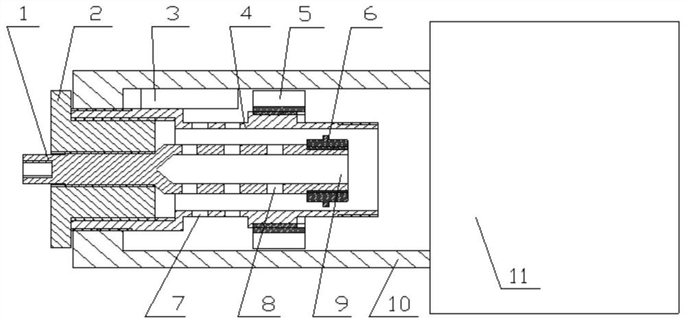
[0023] The present invention provides a ramjet plasma igniter, such as figure 1 As shown, it includes a high voltage electrode 1 , an insulating medium 2 , a low voltage electrode 4 , a rectifier grid 5 , a discharge boss 6 , an annular casing 10 , and a flame nozzle 11 . The insulating medium 2 is made of polytetrafluoroethylene.

[0024] The low-voltage electrode 4 is fixed on the outer circumference of the high-voltage electrode 1 through the insulating medium 2, and a discharge space is formed between the high-voltage electrode 1 and the low-voltage electrode 4; the insulating medium 2 is used to isolate and support the high-voltage electrode 1 and the low-voltage electrode 4. One end of the annular casing 10 is fixed on one end of the outer circumference of the low-voltage electrode 4, and the other end is fixedly connected with the flame nozzle 1...


PUM


Abstract

The invention discloses a ramjet plasma igniter, comprising a high-voltage electrode, an insulating medium, a low-voltage electrode, a rectifier grid, an annular casing and a flame nozzle; the low-voltage electrode is fixed on the outer circumference of the high-voltage electrode through the insulating medium, and the two A discharge space is formed; one end of the annular shell is fixed at one end of the low-voltage electrode, the other end is fixedly connected with the flame nozzle as a flame nozzle, and a swirling space is formed between the annular shell and the low-voltage electrode; the other end of the low-voltage electrode is provided with a rectifier grid; There is a primary airflow hole; the annular casing is provided with a tangential air inlet; the plasma igniter and the combustion chamber share the oil and gas mixed fuel, and the high-speed jet combustible mixture enters from the tangential air inlet, forming a rotation in the swirl space The airflow becomes a direct current to the flame nozzle through the action of the rectifier grid; the combustible mixture enters the discharge space through the primary airflow hole to realize ignition. The invention can realize multiple ignition and sustainable combustion of the ramjet, and meet the wide-area ignition requirement of the engine.

Description

technical field [0001] The invention relates to the technical field of air-breathing engine ignition, in particular to a ramjet plasma igniter. Background technique [0002] Air-breathing ramjets have the characteristics of high specific impulse under supersonic flight conditions, and are ideal power for long-range, high-altitude, and high-speed cruise aircraft. With the development of aircraft toward the direction of large airspace, high speed, and ultra-long distance, the strong requirements for supersonic aircraft with faster flight speed and wider working range, and air-breathing ramjet technology for bombs have become increasingly prominent. The ramjet needs to have fast response, reliable and stable operation, and the ability to fire multiple times in a large airspace. However, when the ramjet engine is in large maneuvering flight, is lean in fuel, is subjected to instantaneous or continuous complex disturbances, or when the angle of attack and sideslip angle are not ...

Claims


Application Information

Patent Timeline
Patent Type & Authority Patents(China)
IPC IPC(8): F02K7/10F02C7/266
CPCF02K7/10F02C7/266
Inventor 付蒙王玉清蒋妮陈静敏张海洲李立翰殷建锋
Owner BEIJING POWER MACHINERY INST
Learn More