A plunger coupling for an obtuse-angle oil groove of a high-pressure oil pump

A technology of high-pressure oil pump and obtuse oil, which is applied to pump elements, parts of pumping devices for elastic fluids, and parts of variable-capacity pumps, etc. , can not operate normally and other problems, to achieve the effect of improving metal components and electrochemical corrosion performance, prolonging life, and improving electrochemical corrosion

Active Publication Date: 2021-11-23
CHANGJIANG WUHAN WATERWAY ENG CO
View PDF43 Cites 0 Cited by
  • Summary
  • Abstract
  • Description
  • Claims
  • Application Information

AI Technical Summary

Problems solved by technology

[0002] The plunger coupling of the high-pressure oil pump is an important part used for engine oil supply. It is driven by the cam to make reciprocating motion in the axial direction, and the purpose of circulating oil supply is achieved through cyclical reciprocating motion. Therefore, it will Long-term friction with the plunger sleeve nested on its outer side. At the same time, in order to control the oil volume, the side of the plunger is provided with an inclined oil groove. The purpose of adjusting the oil volume of a single pump can be achieved by turning the plunger. However, the end of the inner wall of the oil groove It directly collides with the oil during the movement, which also causes the metal debris and corrosive substances mixed in the oil to have the most destructive effect on the end of the inner wall of the oil tank, so the plunger is often caused by erosion and wear on the edge of the oil tank. Not functioning properly, or even scrapped prematurely

Method used


Image

  • A plunger coupling for an obtuse-angle oil groove of a high-pressure oil pump
  • A plunger coupling for an obtuse-angle oil groove of a high-pressure oil pump
  • A plunger coupling for an obtuse-angle oil groove of a high-pressure oil pump

Examples


Embodiment 1

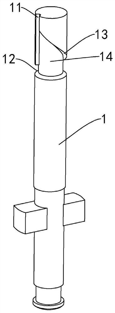
[0041] Process the plunger coupler in which the side walls of the inclined groove 13, the annular groove 12 and the oil outlet groove 11 form an angle of 110° with the bottom surface of the corresponding groove body.

Embodiment 2

[0043]Process the plunger coupling with the side wall of the chute 13, the annular groove 12, and the oil outlet groove 11 forming an angle of 120° with the bottom surface of the corresponding groove body. At the same time, the surface of the plunger body 1 is covered with iron sheets, and the The opening is filled with an appropriate amount of steel balls into the special-shaped tank body 14. The diameter of the steel balls is 0.1mm, and then the opening of the oil outlet tank 11 is closed, and the plunger body 1 is fixed on the vibration platform for vibration treatment. During the vibration process, in order to ensure that each Uniform shot blasting can be achieved in all directions. The plunger body 1 is set to rotate 20 revolutions per minute, the vibration frequency of the vibration platform is 100 Hz, and the vibration time is 30 minutes. After the treatment is completed, the iron sheet is removed to obtain the plunger coupling.

Embodiment 3

[0045] Process the plunger coupling with the side wall of the chute 13, the annular groove 12 and the oil outlet groove 11 forming an angle of 130° with the bottom surface of the corresponding groove body, and at the same time cover the surface of the plunger body 1 with iron sheet, and pass through The opening is filled with an appropriate amount of copper balls and nickel powder in the special-shaped tank body 14. The diameter of the copper balls is 0.5mm, and then the opening of the oil outlet tank 11 is closed, and the plunger body 1 is fixed on the vibration platform for vibration treatment. During the vibration process, In order to ensure uniform shot blasting in each direction, the plunger body 1 is set to rotate 20 revolutions per minute, the vibration frequency of the vibration platform is 200Hz, and the vibration time is 40min. After the treatment is completed, the iron sheet is removed to obtain the plunger coupling.


PUM


Abstract

The present invention proposes a plunger coupling for an obtuse-angle oil tank of a high-pressure oil pump, the plunger coupling includes a plunger body, the plunger body is a cylindrical metal rod, and an oil outlet groove is provided on the side of one end of the plunger body along the axial direction One end of the oil outlet groove communicates with the end of the plunger body, and the other end is closed. The closed end of the oil outlet groove is provided with an annular groove along the circumference of the plunger body, and one side of the end of the oil outlet groove communicates with the end of the plunger body A chute is provided along the surface of the plunger body. One end of the chute communicates with the oil outlet groove, and the other end communicates with the annular groove. The area enclosed by the chute, the annular groove and the oil outlet groove forms a special-shaped groove with the same depth. The angle formed by the side walls of the chute, the annular groove and the oil outlet groove and the bottom surface of the corresponding groove body is an obtuse angle. The structure of the oil groove of the plunger coupling part of the invention is more reasonable, and at the same time, the surface of the oil groove after treatment has better mechanical properties and electrochemical properties, and has good application prospects.

Description

technical field [0001] The invention relates to the technical field of high-pressure oil pump equipment, in particular to a plunger coupling for an obtuse-angle oil groove of a high-pressure oil pump. Background technique [0002] The plunger coupling of the high-pressure oil pump is an important part used for engine oil supply. It is driven by the cam to make reciprocating motion in the axial direction, and the purpose of circulating oil supply is achieved through cyclical reciprocating motion. Therefore, it will Long-term friction with the plunger sleeve nested on its outer side. At the same time, in order to control the oil volume, the side of the plunger is provided with an inclined oil groove. The purpose of adjusting the oil volume of a single pump can be achieved by turning the plunger. However, the end of the inner wall of the oil groove It directly collides with the oil during the movement, which also causes the metal debris and corrosive substances mixed in the oil...

Claims


Application Information

Patent Timeline
Patent Type & Authority Patents(China)
IPC IPC(8): F02M59/02F02M59/44F04B53/00F04B53/14
CPCF02M59/02F02M59/44F02M59/445F04B53/00F04B53/14
Inventor 刘丹亚陈子岸汪航李文琦杨秀春陈安迪
Owner CHANGJIANG WUHAN WATERWAY ENG CO
Why Eureka
Try Eureka