A flow channel design method for a high-efficiency hydraulic manifold

A hydraulic integration and design method technology, applied in design optimization/simulation, computer-aided design, calculation, etc., can solve problems such as low degree of automation, partial loss along the process, and low efficiency, so as to improve design efficiency and energy Efficiency and the effect of reducing manufacturing costs

Active Publication Date: 2022-08-05
HEFEI UNIV OF TECH
View PDF3 Cites 0 Cited by
  • Summary
  • Abstract
  • Description
  • Claims
  • Application Information

AI Technical Summary

Problems solved by technology

However, limited by the mechanical cross-drilling method of the traditional hydraulic manifold to manufacture the internal flow channel, the problems of the process hole cavity, the sudden change of the flow channel cross-section, and the space utilization rate are obvious, resulting in excessive loss along the process and local loss, resulting in hydraulic pressure. Manifold energy inefficiency
[0003] In addition, in the traditional design process, the layout of hydraulic components and the connection of flow channels between ports are manually performed. The low degree of automation leads to insufficient flexibility and low efficiency of the design, and it is impossible to achieve rapid iterative optimization.

Method used


Image

  • A flow channel design method for a high-efficiency hydraulic manifold
  • A flow channel design method for a high-efficiency hydraulic manifold
  • A flow channel design method for a high-efficiency hydraulic manifold

Examples


Embodiment Construction

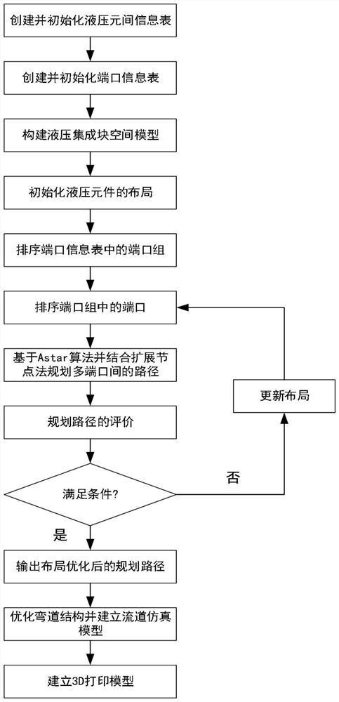
[0048] In this embodiment, as figure 1 As shown in the figure, a flow channel design method for an energy-efficient hydraulic manifold reduces the loss along the flow path and the local loss through layout optimization, inter-port path planning and local flow channel structure optimization, and improves the performance of the hydraulic manifold. energy efficiency, and the design results can be fabricated using 3D printing. Specifically, follow the steps below:

[0049] Step 1. Establish the mathematical model of the hydraulic manifold:

[0050] Step 1.1. Determine the hydraulic component model on the hydraulic manifold according to the hydraulic schematic diagram, and create and initialize the hydraulic component information table HC={hc 1 ,hc 2 ,...,hc i ,...,hc I }, where hc i is the information set of the ith hydraulic element, I is the total number of hydraulic elements; and there are:

[0051]

[0052] Among them, because of the different geometric shapes of hyd...


PUM


Abstract

The invention discloses a flow channel design method for a high-energy-efficiency hydraulic integrated block. , based on the Astar algorithm and combined with the extended node method to plan the paths between the ports, use the optimization algorithm to iteratively layout to obtain the path set; then optimize the local structure of the curve and wall thickness and establish a complete flow channel simulation model; finally establish the hydraulic manifold block 3D printed model of the runner. Through layout optimization, path planning between ports and local flow channel structure optimization, the invention can reduce the loss along the path and the local loss of the flow channel, improve the energy efficiency of the hydraulic integrated block, and the design result can be manufactured by 3D printing.

Description

technical field [0001] The invention relates to the technical field of hydraulic manifold design; in particular, it relates to a flow channel design method for a high-energy-efficiency hydraulic manifold, which is used to reduce the loss along the flow path and the local loss and improve the energy efficiency of the hydraulic manifold. Background technique [0002] Hydraulic transmission technology has the advantages of high power, small size and stable transmission, and is widely used in aerospace, forming equipment and construction machinery and other fields. The hydraulic manifold has become an important component in hydraulic transmission due to its compact structure, convenient installation, easy maintenance, low leakage and low vibration and noise. However, due to the fact that traditional hydraulic manifolds use mechanical cross-drilling to manufacture internal flow channels, the problems of process hole volume, sudden change of flow channel cross-section, and space u...

Claims


Application Information

Patent Timeline
Patent Type & Authority Patents(China)
IPC IPC(8): G06F30/17G06F30/28G06F111/06G06F111/10G06F113/08G06F119/14
CPCG06F30/17G06F30/28G06F2113/08G06F2119/14G06F2111/10G06F2111/06
Inventor 黄海鸿钱程金瑞李磊刘志峰
Owner HEFEI UNIV OF TECH
Why Eureka
Try Eureka