Rotary pouring machine for casting machining

A rotary and pouring machine technology, applied in the field of casting processing, can solve problems such as difficulty in demolding, adhesion of the outside of the mold, danger to workers' personal safety, etc., and achieve the effect of simple and convenient replacement of molds and easy access.

Active Publication Date: 2021-05-11
临沂凯士彼机械有限公司
View PDF16 Cites 4 Cited by
  • Summary
  • Abstract
  • Description
  • Claims
  • Application Information

AI Technical Summary

Problems solved by technology

[0002] Pouring is a modern production process that injects molten metal and other molten liquid into the mold and then casts metal parts. Most of the existing pouring methods use tools to hold the container containing the molten metal, and then move the container Go to the mold, then pour the molten metal stored in the container into the mold. This pouring method is not only dangerous to the personal safety of the workers, but also when the molten metal is poured into the mold, the mold is placed on the iron sand. , in most cases, the mold is not placed in a vertical state, and it is very easy for the molten metal to splash and leak. This is because the mass of the metal is large, and the weight of the container itself makes the worker use his own strength to dump the molten metal. It cannot be accurately poured into the mold, resulting in a lot of waste of molten metal, and after the pouring is completed, a large amount of metal will remain at the sprue of the mold. After the metal is cooled and formed, it is easy to stick to the outside of the mold, making demoulding Difficulty, therefore, we propose a rotary pouring machine for casting processing that prevents mold shaking and has stable clamping

Method used


Image

  • Rotary pouring machine for casting machining
  • Rotary pouring machine for casting machining
  • Rotary pouring machine for casting machining

Examples


Embodiment Construction

[0021] The following will clearly and completely describe the technical solutions in the embodiments of the present invention with reference to the accompanying drawings in the embodiments of the present invention. Obviously, the described embodiments are only some, not all, embodiments of the present invention. Based on the embodiments of the present invention, all other embodiments obtained by persons of ordinary skill in the art without making creative efforts belong to the protection scope of the present invention.

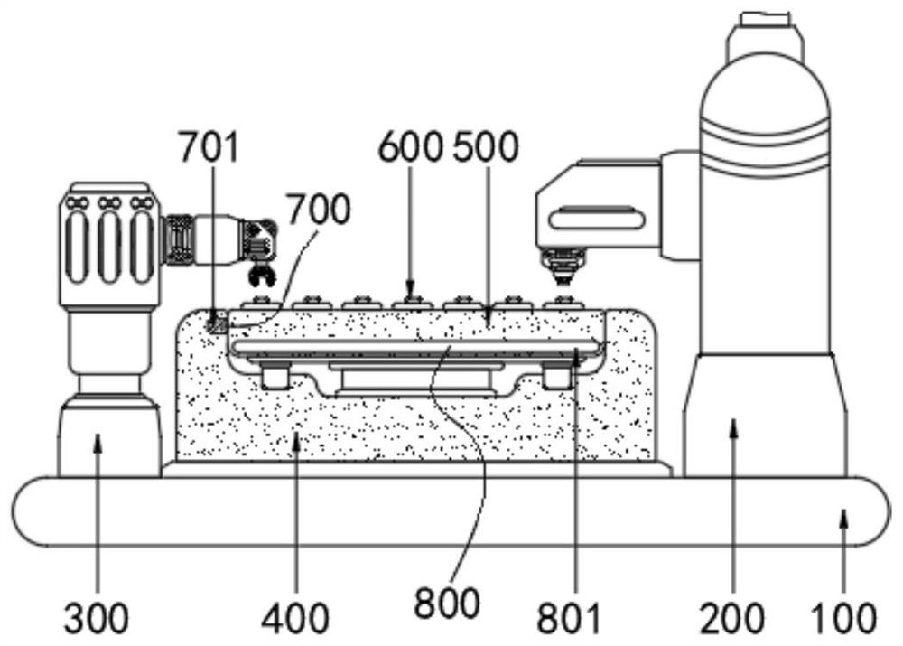
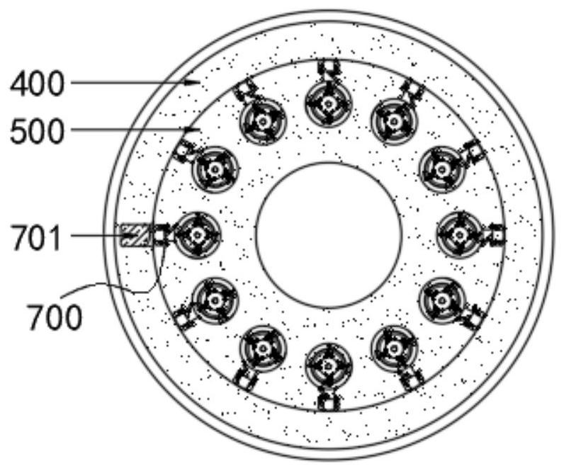
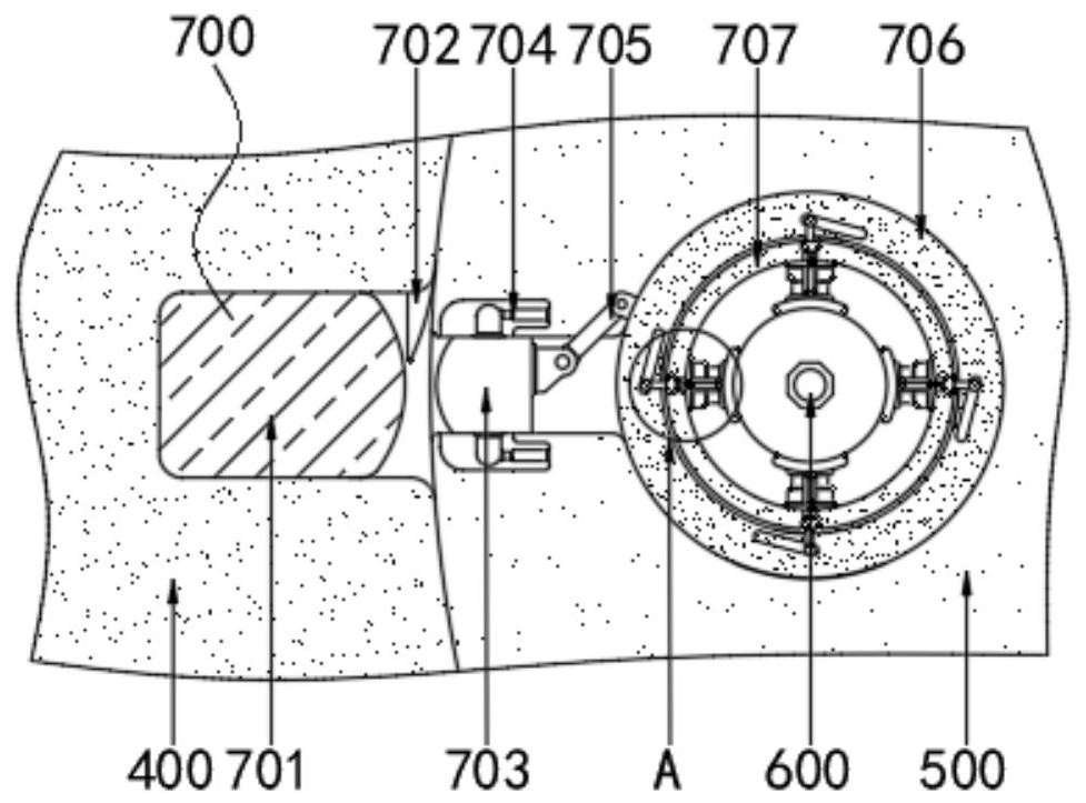
[0022] see Figure 1-7 , a rotary pouring machine for casting processing, comprising a base 100, a liquid injection column 200, a mechanical arm 300, a box body 400, a rotary disc 500, a mold 600, a clamping assembly 700 and a buffer assembly 800, the top of the base 100 and the injection The liquid column 200 is fixedly connected, the box body 400 is fixedly connected to the top of the base 100 on the left side of the liquid injection column 200, the top of t...


PUM


Abstract

The invention relates to the technical field of casting machining, and discloses a rotary casting machine for casting machining. The rotary casting machine for casting machining comprises a base, a liquid injection column, a mechanical arm, a box body, a rotary disc, a mold, a clamping assembly and a buffer assembly, wherein the top end of the base is fixedly connected with the liquid injection column; the box body is located on the left side of the liquid injection column and fixedly connected with the top end of the base; the top end of the inner wall of the box body is movably connected with the rotary disc; the top end of the inner wall of the rotary disc is movably connected with the mold; the inner wall of the rotary disc is movably connected with the buffer assembly; the left side of the rotary disc is movably connected with the clamping assembly; and a driving motor is arranged in the rotary disc and drives the rotary disc to rotate when running; Compared with traditional manual pouring, the rotary casting machine for casting machining is accurate during casting, the phenomenon that molten metal splashes is not prone to being generated, and the mold does not shake greatly in the initial rising stage, so that the phenomenon that the molten metal in the mold splashes is avoided.

Description

technical field [0001] The invention relates to the technical field of casting processing, in particular to a rotary pouring machine for casting processing. Background technique [0002] Pouring is a modern production process that injects molten metal and other molten liquid into the mold and then casts metal parts. Most of the existing pouring methods use tools to hold the container containing the molten metal, and then move the container Go to the mold, then pour the molten metal stored in the container into the mold. This pouring method is not only dangerous to the personal safety of the workers, but also when the molten metal is poured into the mold, the mold is placed on the iron sand. , in most cases, the mold is not placed in a vertical state, and it is very easy for the molten metal to splash and leak. This is because the mass of the metal is large, and the weight of the container itself makes the worker use his own strength to dump the molten metal. It cannot be ac...

Claims


Application Information

Patent Timeline
Patent Type & Authority Applications(China)
IPC IPC(8): B22D35/04B22D33/02B22D33/06
CPCB22D35/04B22D33/02B22D33/06
Inventor 崔华波
Owner 临沂凯士彼机械有限公司
Why Eureka
Try Eureka