
A high current channel selector pdu system

A channel selection, high-current technology, applied in current collectors, circuits, charging stations, etc., can solve the problems of complex lines, poor flexibility, and high calorific value, and achieve flexible distribution, strong applicability, and reduced calorific value.

Active Publication Date: 2022-05-17
JIANGSU WANBANG DEHE NEW ENERGY TECH CO LTD +1
View PDF5 Cites 0 Cited by
  • Summary
  • Abstract
  • Description
  • Claims
  • Application Information

AI Technical Summary

Problems solved by technology

[0004] In order to solve the problems existing in the prior art of using multiple relays or multi-channel relays for power distribution, fixed wiring, complex wiring, poor flexibility, and high heat generation, the present invention proposes a large current channel selector PDU system, Solved the above technical problems

Method used


Image

  • A high current channel selector pdu system
  • A high current channel selector pdu system
  • A high current channel selector pdu system

Examples


Embodiment 1

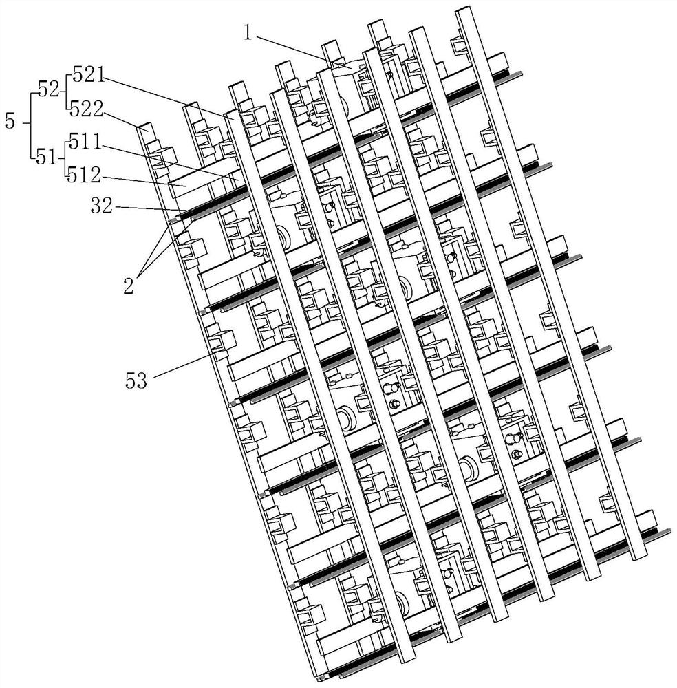
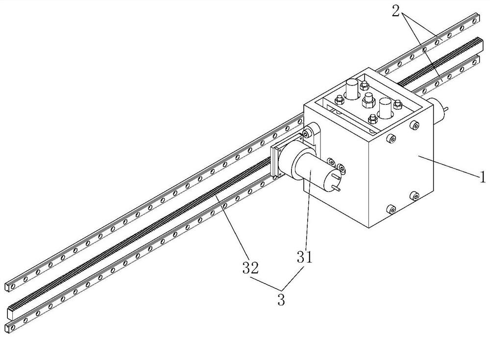
[0038] like Figure 1-6 As shown, this embodiment provides a high-current channel selection PDU system, including a PDU robot module 1 and an external channel 5. The external channels 5 are arranged in an array on the outer circumference of the PDU robot module 1, and the PDU robot module 1 moves to the workstation. , the electrode unit 12 in the PDU robot module 1 extends out and contacts with the external channel 5 to form an electrical connection.

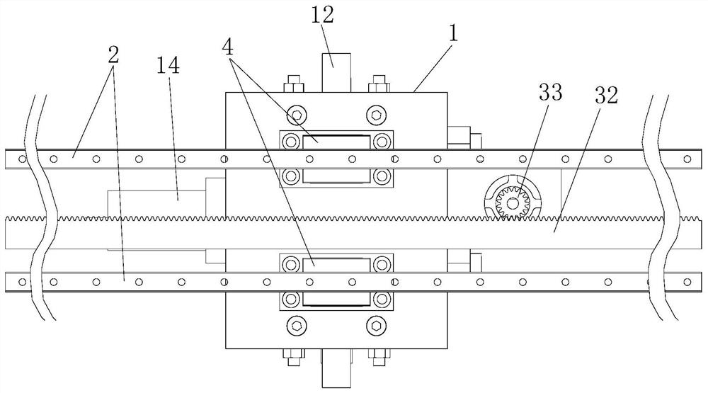
[0039] The PDU robot module 1 includes a moving carrier 11, an electrode unit 12 and a driving member 14. The electrode unit 12 includes an input electrode 121 and an output electrode 122. The input electrode 121 and the output electrode 122 are electrically connected, and the input electrode 121 and the output electrode 122 are driven Under the driving action of the driving element 14, the element 14 extends from the moving carrier 11 to connect the external circuit; when the input electrode 121 and the output electrode 122 ret...

Embodiment 2

[0051] like Figure 7 As shown, this embodiment is basically the same as the first embodiment, and the only difference lies in the structure of the transmission assembly 15 . In this embodiment, the transmission assembly 15 includes a lead screw 151 and a nut 152. There is one lead screw 151 and two nuts 152. Both ends of the lead screw 151 are rotatably mounted on the side plate 112, and the two nuts 152 are symmetrical The two nuts 152 are arranged on the screw rod 151, and the two ends of the screw rod 151 are anti-jammed, so that the two nuts 152 can drive the two brackets 13 to move toward each other or backwards synchronously.

[0052] Further, a first helical gear 153 is connected to the driving end of the driving member 14 , a second helical gear 154 is provided on the screw rod 151 , and the first helical gear 153 and the second helical gear 154 are engaged.

Embodiment 3

[0054] like Figure 8 As shown, this embodiment is basically the same as the first embodiment, the only difference is that, in this embodiment, the transmission assembly 15 can be omitted, and the driving member 14 can be configured as a telescopic driving device. The driving part 14 includes a driving part 141 and a telescopic part 142. The driving part 141 and the telescopic part 142 are fixedly connected to the two brackets 13 respectively. The driving member 14 can be selected from but not limited to air cylinders, hydraulic cylinders, electric cylinders, and frame-type electromagnets.


PUM


Abstract

The invention relates to the charging field, in particular to a large current channel selector PDU system. It includes: a PDU robot module, the PDU robot module includes a mobile carrier and an electrode unit arranged on the mobile carrier, the mobile carrier drives the electrode unit to move to the station, and the electrode unit telescopically contacts the external channel to form Electrical connection; external channels, the external channels are arranged outside the PDU robot module, the external channels include input channels and output channels, the input channels and / or the output channels are at least two groups, the input channels The channels are set in one-to-one correspondence with the PDU robot modules, and the input channels and the output channels are arranged in a staggered array on the same side. It solves the problems existing in the prior art that multiple relays or multiple relays are used for power distribution, fixed wiring is required, the circuit is complicated, the flexibility is poor, and the heat generation is high.

Description

technical field [0001] The invention relates to the field of charging, in particular to a high-current channel selector PDU system. Background technique [0002] When using charging piles to charge electric vehicles, electric vehicles with different power requirements will be encountered. When a small electric vehicle needs low power, the charging pile will waste its own power supply capacity resources, or when a large electric vehicle needs more power than a single charging pile's own power supply capacity, the charging time will be longer. [0003] In the existing flexible power distribution system of the charging stack, the core unit PDU adopts a single relay / contactor to form an MxN array, or uses a plurality of fixed multi-contact relays / contactors, which are essentially a kind of Array of MxN relay groups. The disadvantage of directly using the relay array is that the amount of relays is large, the cost is high, and MxN complex control circuits are required. This sol...

Claims


Application Information

Patent Timeline
Patent Type & Authority Patents(China)
IPC IPC(8): B60L53/30H01R13/629H02J7/00
CPCB60L53/30H01R13/629H02J7/0045Y02T10/70Y02T10/7072Y02T90/12
Inventor 袁江徽李明张程飞张舟李德胜郑隽一张育铭
Owner JIANGSU WANBANG DEHE NEW ENERGY TECH CO LTD
Learn More