Friction experiment device in thermal vacuum environment

An experimental device, thermal vacuum technology, applied to measuring devices, material analysis through optical means, instruments, etc., can solve problems such as difficulty in ensuring coaxiality, large required space, and short transmission chains

Pending Publication Date: 2021-05-11
ZHEJIANG UNIV OF TECH
View PDF0 Cites 0 Cited by
  • Summary
  • Abstract
  • Description
  • Claims
  • Application Information

AI Technical Summary

Problems solved by technology

[0008] The purpose of the present invention is to solve the problem that the vacuum motor of the existing ground vacuum driving and loading equipment cannot meet the speed, torque and working temperature required for the experiment, and the transmission chain required for external driving and loading of the vacuum box is long and the coaxiality is difficult to guarantee , the required space is large, the loading and unloading has a certain delay, and the corresponding vacuum box needs to be customized. A short transmission chain, high coaxiality, small required space, good heat insulation and fast loading speed are proposed. Tribological Experimental Apparatus in Thermal Vacuum Environment

Method used


Image

  • Friction experiment device in thermal vacuum environment
  • Friction experiment device in thermal vacuum environment
  • Friction experiment device in thermal vacuum environment

Examples


Embodiment Construction

[0033] The present invention will be further described below in conjunction with accompanying drawing:

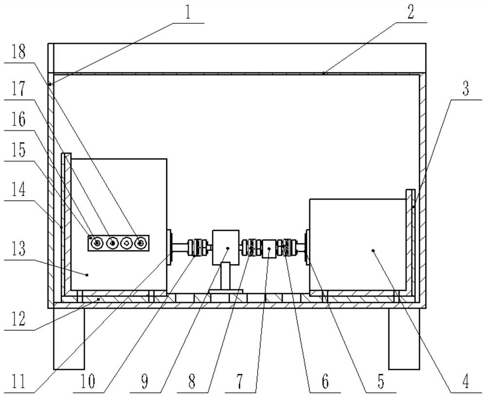
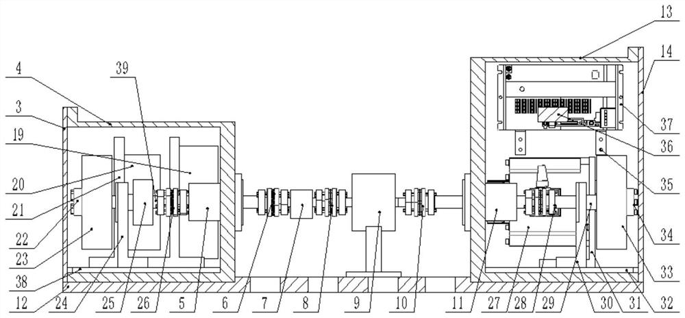
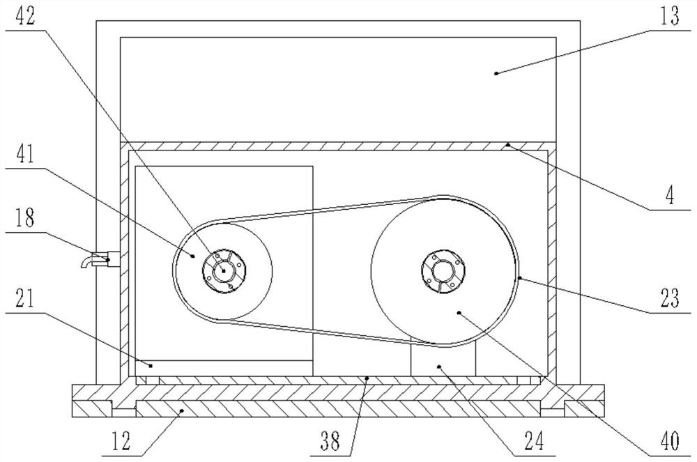
[0034] Such as Figure 1-5 As shown, a friction experiment device in a thermal vacuum environment includes a temperature-controllable vacuum box 2, a loading box 4, a general installation base plate 12, a magnetic fluid seal shaft 5 at the loading end, a third heat-insulated coupling 6, and a torque sensor 7 , the first thermal insulation coupling 8, the test piece 9, the second thermal insulation coupling 10, the magnetic fluid seal shaft 11 at the driving end, the normal temperature and pressure tank 13 at the driving end, the driving device and the loading device, the general installation base plate 12 is fixed on the inner bottom plate of the temperature-controllable vacuum box 2, the driving end normal temperature and pressure box 13, the test piece 9 and the loading box 4 are all fixedly installed on the general installation bottom plate 12, the test piece 9 is provid...


PUM


Abstract

The invention discloses a friction experiment device in a thermal vacuum environment. The device comprises a temperature-controllable vacuum box, a loading box, a total mounting bottom plate, a loading end magnetofluid sealing shaft, a third heat insulation coupling, a torque sensor, a first heat insulation coupling, a test piece, a second heat insulation coupling, a driving end magnetofluid sealing shaft, a driving end normal temperature and normal pressure box, a driving device and a loading device. According to the invention, a servo motor can be arranged in a normal-temperature and normal-pressure box formed by fixing the open end surface of the normal-temperature and normal-pressure box and a normal-temperature and normal-pressure box end cover 14 through bolts so that under the condition that the large-torque and high-rotating-speed test requirements can be met, driving and loading outside a vacuum tank are not needed; and when the test is completed, a special vacuum tank does not need to be customized, only the mounting platform needs to be put down, the length of a transmission chain is greatly shortened, and the coaxiality is easy to guarantee.

Description

technical field [0001] The invention relates to the field of driving and loading tests in a thermal vacuum environment, and more specifically relates to a friction test device in a thermal vacuum environment. Background technique [0002] There is a brake applicable to the aerospace field, and the purpose of the device is to decelerate the rotating shaft until it stops rotating. The main working environment of this type of brake is a thermal vacuum environment. Its main principle is: use the friction pair in the brake to generate and prevent the torque of the rotating shaft, so that the target shaft decelerates until it stops rotating. In order to study the performance, life and other characteristics of the brake under different working conditions, different environments, and different steering directions, it is necessary to carry out corresponding simulation tests on the ground. [0003] In order to complete the ground simulation test of the brake, it is necessary to desig...

Claims


Application Information

Patent Timeline
Patent Type & Authority Applications(China)
IPC IPC(8): G01N21/84
CPCG01N21/84
Inventor 叶必卿李蒙正单晓杭李研彪张利
Owner ZHEJIANG UNIV OF TECH
Why Eureka
Try Eureka