Cutting motion control method and device, and computer readable storage medium

A technology of cutting motion and control method, which is applied in the field of computer-readable storage media and cutting motion control, can solve problems such as the inability to quickly solve short-segment motion vibration, unsuitable for mass production, and inability to modify, so as to improve cutting efficiency and use Experience and modify the effect of low cost

Active Publication Date: 2021-05-11
HANGZHOU ECHO SCI TECH
View PDF4 Cites 1 Cited by
  • Summary
  • Abstract
  • Description
  • Claims
  • Application Information

AI Technical Summary

Problems solved by technology

The advantage of this method is that you can get the best acceleration acc` and the best moving speed Vel` tables for different moving distances of the machine through testing. The disadvantage is that different machines need to be tested once to get the best acceleration acc` and the best Movement speed Vel` table, very inconvenient, not suitable for mass production
Furthermore, when the number of heads of the machine increases or the cutting load changes, since the look-up table data is the best acceleration acc` and the best moving speed Vel` of the different moving distances of the machine measured when the machine is not changed, After the machine parameters are changed, the previous table is not s

Method used


Image

  • Cutting motion control method and device, and computer readable storage medium
  • Cutting motion control method and device, and computer readable storage medium
  • Cutting motion control method and device, and computer readable storage medium

Examples


Embodiment approach

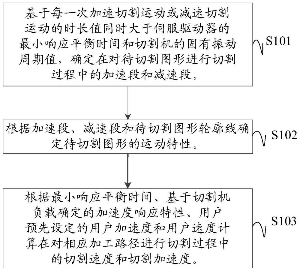
[0114] As an optional implementation of this embodiment, step B1 determines each processing path according to the total length of each processing path, the take-off speed, the minimum response balance time, the acceleration response characteristics and the pre-built S-shaped velocity calculation relationship An implementation of the leading endpoint velocity and trailing endpoint velocity may include:

[0115] The processing paths are sorted according to the order from the starting point to the ending point of the contour line of the figure to be cut, and the processing path including the starting point is taken as the first processing path.

[0116] Determine the initial speed of the first and last endpoints of each processing path according to the relationship between the rotation angles, and calculate the acceleration value of the corresponding processing path according to the acceleration response characteristics, speed change relationship and user acceleration.

[0117] T...


PUM


Abstract

The invention discloses a cutting motion control method and device, and a computer readable storage medium. The method comprises the following steps: determining an acceleration section and a deceleration section in the cutting process of a to-be-cut graph on the basis that the duration value of each acceleration cutting motion or deceleration cutting motion is larger than the minimum response balance time of a servo driver and the natural vibration period value of a cutting machine at the same time; determining a processing path of the to-be-cut graph according to the contour line of the to-be-cut graph, and determining an acceleration section and a deceleration section of the corresponding processing path according to the minimum response balance time, an acceleration response characteristic determined based on the rigidity of the cutting machine, and a user acceleration and a user speed preset by a user; and calculating the maximum cutting speed and the maximum cutting acceleration in the cutting process of the corresponding machining path. The machining path with the known length can be stably cut within the shortest time, materials can be cut in a high-acceleration, high-movement-speed and low-vibration mode so that the cutting quality can be guaranteed, and the cutting efficiency and the cutting precision are effectively improved.

Description

technical field [0001] The present application relates to the technical field of flexible material cutting, in particular to a cutting motion control method, device and computer-readable storage medium. Background technique [0002] When cutting flexible materials, the corresponding CAD graphic outline is often represented by a set of discrete and sequential points, and the trajectory obtained by connecting these discrete points in sequence is described by these sequential point sets contour. The flexible material cutting machine performs the cutting operation according to the cutting trajectory obtained by connecting these discrete points in sequence. On the whole, the point set depicts a variety of complex and diverse outlines, so the point set is very complex and diverse. From a local point of view, the contour lines described by these complex and diverse point sets are represented by line segments composed of two adjacent points, so the movement of the cutting machine ...

Claims


Application Information

Patent Timeline
IPC IPC(8): G05B19/4097
CPCG05B19/4097G05B2219/32153
Inventor 伍郁杰白燕吴超
Owner HANGZHOU ECHO SCI TECH
Why Eureka
Try Eureka