
Layered stacking type high-performance electronic transformer and implementation method thereof

An electronic transformer, stacking technology, applied in inductor/transformer/magnet manufacturing, transformer/inductor cooling, transformer/inductor components, etc., can solve problems such as difficult heat dissipation, poor performance consistency, and irregular shape.

Pending Publication Date: 2021-05-11
深圳市柔性磁电技术有限公司
View PDF0 Cites 2 Cited by
  • Summary
  • Abstract
  • Description
  • Claims
  • Application Information

AI Technical Summary

Problems solved by technology

[0006] The object of the present invention is to provide a high-performance electronic transformer in a layered stacking mode and its realization method, which has the advantages of high production efficiency, good heat dissipation and insulation withstand voltage, and solves the problem that the heat dissipation path is from the inner copper wire to the insulating material and then To the outer copper wire and then to the outer magnetic core, such a multi-layer cycle, the heat is constantly rising, the heat is accumulated, it is not easy to dissipate heat, and the shape is irregular, resulting in poor performance consistency.

Method used


Image

  • Layered stacking type high-performance electronic transformer and implementation method thereof
  • Layered stacking type high-performance electronic transformer and implementation method thereof
  • Layered stacking type high-performance electronic transformer and implementation method thereof

Examples


Embodiment Construction

[0027] The following will clearly and completely describe the technical solutions in the embodiments of the present invention with reference to the accompanying drawings in the embodiments of the present invention. Obviously, the described embodiments are only some, not all, embodiments of the present invention. Based on the embodiments of the present invention, all other embodiments obtained by persons of ordinary skill in the art without making creative efforts belong to the protection scope of the present invention.

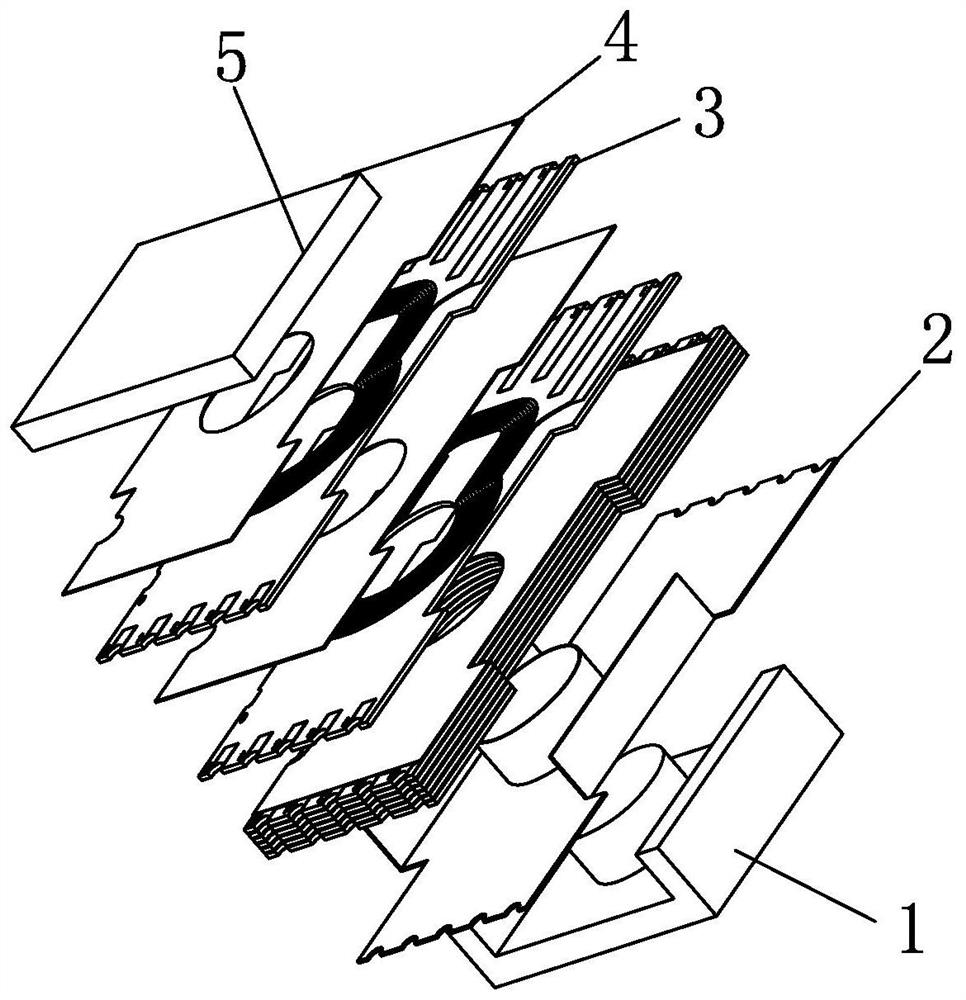
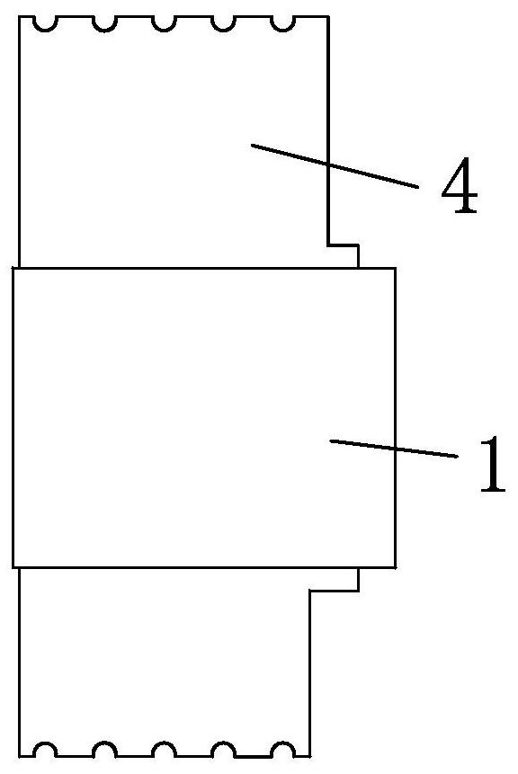
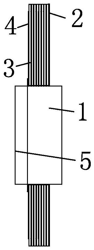
[0028] see Figure 1-8 As shown, the present invention provides a technical solution: a high-performance electronic transformer in a layered stacking manner, including a lower magnetic core 1, a skeleton 2 is installed on the top of the lower magnetic core 1, and a PCB board 3 is installed on the top of the skeleton 2, An insulating sheet 4 is installed on the top of the PCB board 3, and an upper magnetic core 5 is installed on the top of the insulating sheet ...


PUM


Abstract

The invention relates to the technical field of electronic components, and discloses a layered stacking type high-performance electronic transformer and an implementation method thereof. The layered stacking type high-performance electronic transformer comprises a lower magnetic core, and a framework is installed at the top of the lower magnetic core; a PCB is installed at the top of the framework, an insulating sheet is installed at the top of the PCB, an upper magnetic core is installed at the top of the insulating sheet, and the upper magnetic core and a lower magnetic core are fixed in a contact mode; each layer of coil is stacked in a parallel mode, so that the number of stacked layers can be adjusted and matched according to needs of users, flexibility is high, meanwhile, reserved gaps exist between the coils, heat is not concentrated, layered heat dissipation is achieved, the heat dissipation area and heat dissipation channels are large, and temperature rise is reduced; after the novel parallel groove rack is adopted, the creepage distance and the insulating and voltage-resisting effects are good, heat accumulation is avoided, heat dissipation is not easy, the problem of poor performance consistency caused by irregular forms is solved, and the heat dissipation performance, the flexibility and the performance consistency of the device are improved.

Description

technical field [0001] The invention relates to the technical field of electronic components, in particular to a high-performance electronic transformer in a layered stacking manner and a realization method thereof. Background technique [0002] Electronic transformer, also known as electronic power transformer, is an electronic device that transfers energy and converts power, and is also a commonly used device in circuits. Electronic transformers are generally made of magnetic cores, skeletons, copper wires, insulating tape, etc. Conventionally, the method of winding copper wire is adopted, from the inside to the outside, a layer of copper wire is wound on the bottom layer of the skeleton to form a spiral coil, and then the pins of the copper wire are inserted into the insulating sheath and led to the pin end, and then a layer of insulation is wound. Tape, and then wind a layer of coils, then put the pins of the copper wires into the insulating sheath and lead them to the ...

Claims


Application Information

Patent Timeline
IPC IPC(8): H01F27/28H01F27/08H01F27/34H01F41/098H01F41/04
CPCH01F27/08H01F27/2804H01F27/2876H01F27/34H01F41/041H01F2027/2809H01F41/098
Inventor 董右云田正强
Owner 深圳市柔性磁电技术有限公司
Learn More