A shielding frame steel mesh opening method, device, electronic equipment and storage medium

A shielding frame and stencil technology, which is applied in the direction of assembling printed circuits, printed circuits, and electrical components with electrical components, can solve problems such as hidden dangers of device collisions, insufficient stress of stencils, and different welding effects, and achieve collision avoidance and stress distribution. Reasonable and competitive effect

Active Publication Date: 2022-04-01
VAYO SHANGHAI TECH
View PDF6 Cites 0 Cited by
  • Summary
  • Abstract
  • Description
  • Claims
  • Application Information

AI Technical Summary

Problems solved by technology

[0004] The welding of the shielding frame needs to design the corresponding stencil opening on the PCB stencil design, and different opening designs will lead to different welding effects
[0005] At present, the solder pads of the shielding frame are printed with solder paste through the opening of the stencil. The opening method of the stencil opening of the shielding frame is to directly use the pads of the shielding frame in the PCB design data for opening. The stencil opening obtained by this method, During welding, there will be problems such as insufficient steel mesh stress, difficulty in removing tin, and hidden dangers of device collision.

Method used


Image

  • A shielding frame steel mesh opening method, device, electronic equipment and storage medium
  • A shielding frame steel mesh opening method, device, electronic equipment and storage medium
  • A shielding frame steel mesh opening method, device, electronic equipment and storage medium

Examples


Embodiment 1

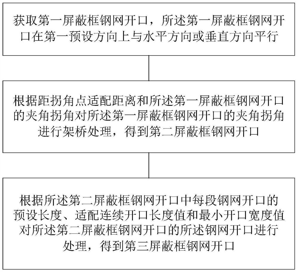
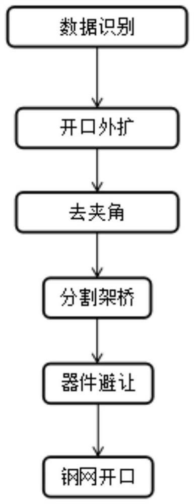
[0062] See figure 1 and figure 2 , figure 1 It is a schematic flow chart of a method for opening a shielding frame stencil provided by an embodiment of the present invention, figure 2 It is a schematic flow chart of another method for opening a shielding frame stencil provided by an embodiment of the present invention. This embodiment provides a method for opening a shielding frame stencil. The method for opening a shielding frame stencil may include steps 1 to 3, wherein :

[0063] Step 1. Obtain the opening of the steel mesh of the first shielding frame, and the opening of the steel mesh of the first shielding frame is parallel to the horizontal direction or the vertical direction in a first preset direction.

[0064] Specifically, the size of the steel mesh opening of the first shielding frame should be able to meet the welding quality, and the steel mesh opening of the first shielding frame is parallel to the horizontal direction or the vertical direction in the first...

Embodiment 2

[0117] In order to better understand the shielding frame steel mesh opening method provided by the present invention, a specific shielding frame steel mesh opening method is also provided on the basis of the above embodiments, the shielding frame steel mesh opening method includes:

[0118] S1. Obtain all pad information from PCB design data, including device coordinates, outer frame, image information, etc. Take out the pad information of the shielding frame. Since the pads of the shielding frame in this example are in a horizontal state, there is no need to perform zeroing processing, or the zeroing rotation angle is 0 degrees. Set the processed pad information of the shielding frame as Preset shielding frame stencil openings.

[0119] S2. In the width direction, expand the acquired preset shielding frame stencil opening by 0.1 mm along the inside and outside respectively, so as to update the preset shielding frame steel mesh opening.

[0120]S3. Take out the coordinates of...

Embodiment 3

[0133] See Figure 17 , Figure 17 It is a schematic structural diagram of a shielding frame steel mesh opening device provided by an embodiment of the present invention. The shielding frame stencil opening device includes:

[0134] An acquisition module, configured to acquire the steel mesh opening of the first shielding frame, where the steel mesh opening of the first shielding frame is parallel to the horizontal direction or the vertical direction in the first preset direction;

[0135] The first bridging processing module is configured to perform bridging processing on the included corner of the steel mesh opening of the first shielding frame according to the fitting distance from the corner point and the included corner of the steel mesh opening of the first shielding frame to obtain the second shielding frame Stencil opening;

[0136] The second bridging processing module is used to adjust the stencil of the second shielding frame stencil opening according to the pres...


PUM


Abstract

The invention discloses a shielding frame steel mesh opening method, device, electronic equipment and storage medium. The method includes: obtaining the first shielding frame steel mesh opening; The included corners of the openings bridge the included corners of the first shielding frame stencil openings to obtain the second shielding frame stencil openings; The preset length, the adaptive continuous opening length value and the minimum opening width value perform bridging processing on the stencil opening of the second shielding frame stencil opening to obtain a third shielding frame stencil opening. The shielding frame stencil opening method of the present invention can make the stress distribution of the finally generated stencil opening scheme reasonable, facilitate tin removal, and can effectively avoid the hidden danger of shielding frame and device collision, avoid human intervention, and reduce production costs. The error rate reduces the production cost of the enterprise and improves the competitiveness of the product.

Description

technical field [0001] The invention belongs to the technical field of printed circuit boards, and in particular relates to a method, device, electronic equipment and storage medium for opening a steel mesh of a shielding frame. Background technique [0002] The rapid development of the electronic manufacturing industry has made highly integrated and high-density electronic products more and more widely used, which has also caused many electromagnetic interference problems. In order to solve such problems, it is necessary to use shielding covers in hardware design to prevent external radiation and interfered with by radiation. A shield is a tool used to shield electronic signals. The function is to shield the influence of external electromagnetic waves on the internal circuit and the external radiation of electromagnetic waves generated inside. [0003] The shielding cover currently used is generally composed of two modules, namely a shielding frame (frame) and a shielding...

Claims


Application Information

Patent Timeline
Patent Type & Authority Patents(China)
IPC IPC(8): H05K3/12H05K3/34
CPCH05K3/1225H05K3/1233H05K3/341H05K2201/10371H05K2203/04
Inventor 武纪宏刘继硕钱胜杰刘丰收
Owner VAYO SHANGHAI TECH
Why Eureka
Try Eureka