Vacuum partition scraper type continuous defoaming machine

A scraper type, defoaming machine technology, applied in the direction of foam dispersion/prevention, can solve the problems of missing raw material temperature control, raw material waste, secondary pollution of raw materials, etc., to achieve high defoaming treatment efficiency, good defoaming effect, reduce The effect of cost

Pending Publication Date: 2021-05-14
绵阳世诺科技有限公司
View PDF3 Cites 0 Cited by
  • Summary
  • Abstract
  • Description
  • Claims
  • Application Information

AI Technical Summary

Problems solved by technology

The current degassing process is performed in static sealed tanks and motor-driven stirring paddles, which has extremely low production capacity, high probability of secondary pollution of raw materials, and extremely serious waste of raw materials
[0003] Chinese patent CN 206424637 U discloses a "continuous vacuum defoaming and degassing device". This structure will cause blockage for extremely high viscosity slurry and lose its function, and the temperature control of the raw material is missing due to the lack of an outer layer, and the efficiency is low.
[0004] Chinese patent CN 107774016 A discloses an "on-line vacuum degassing device". This structure cannot degas the slurry with extremely high viscosity, and lacks the outer layer to control the temperature of the raw material, resulting in low efficiency.
[0006] The appeal patent can conveniently realize online continuous degassing, but there is insufficient degassing time for the slurry with high surface tension. For the degassed slurry, the impact of the nozzle of the discharge pipe is easy to generate air bubbles again. Avoid, and eventually lead to certain limitations in the application of slurry industry

Method used


Image

  • Vacuum partition scraper type continuous defoaming machine
  • Vacuum partition scraper type continuous defoaming machine
  • Vacuum partition scraper type continuous defoaming machine

Examples


Embodiment 1

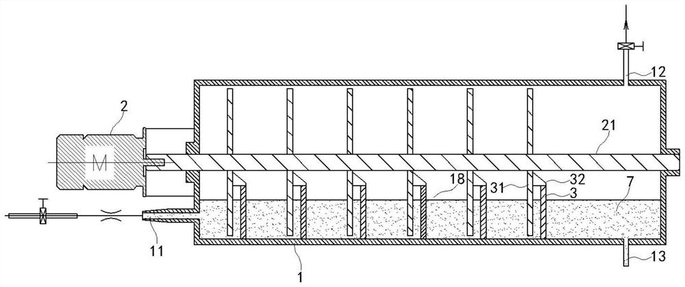
[0058] Such as figure 1 As shown, a vacuum partition scraper type continuous degassing machine of the present embodiment comprises a horizontally arranged cylindrical separation tank 1, and the separation tank 1 is provided with a feed pipe 11, a vacuum pipe 12 and a discharge port 13; the end of the separation tank 1 The motor 2 drives the main shaft 21 coaxial with the separation tank 1 in the separation tank 1 to rotate; the five baffles 3 arranged at the bottom of the separation tank 1 divide the lower part of the separation tank 1 into six slurry chambers 18, and the feed pipe 11 It communicates with the first slurry chamber 18, and the discharge port 13 is located at the last slurry chamber 18; it is fixed on the main shaft 21 and does not contact the inner wall of the separation tank 1 with 5 belt trays 31, and the belt trays 31 are located at There is a discharge gap between the feed end side of the baffle 3 and the baffle 3 ; the slurry scraper 32 is arranged above t...

Embodiment 2

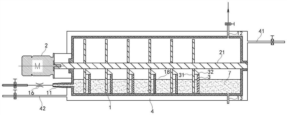
[0062] Such as figure 2 As shown, this embodiment is a further optimization of Embodiment 1. The outer surface of the separation tank 1 is provided with a cooling and heating medium circulation chamber 4, and the cooling and heating medium circulation chamber 4 is provided with a cooling and heating medium inlet 42 or a cooling and heating medium outlet 41. A cold and hot medium outlet 41 or a cold and hot medium inlet 42 are arranged below the medium circulation chamber 4, and the temperature in the separation tank 1 can be adjusted by feeding the refrigerant or heat medium, so that the separation tank 1 is always in the process temperature range for the degassing of the slurry 7, which is more It is beneficial to the defoaming of the slurry 7.

Embodiment 3

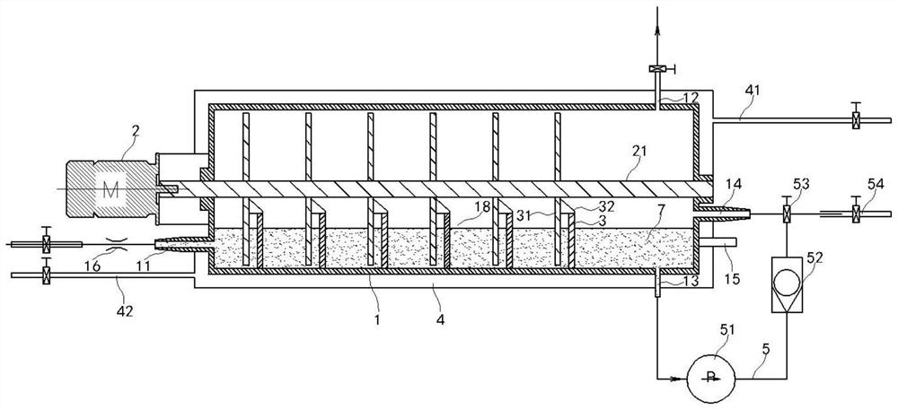
[0064] Such as image 3 As shown, this embodiment is a further optimization of Embodiment 1. The outer surface of the separation tank 1 is provided with a cooling and heating medium circulation chamber 4, and the cooling and heating medium circulation chamber 4 is provided with a cooling and heating medium inlet 42 or a cooling and heating medium outlet 41. A cold and hot medium outlet 41 or a cold and hot medium inlet 42 are arranged below the medium circulation chamber 4, and the temperature in the separation tank 1 can be adjusted by feeding the refrigerant or heat medium, so that the separation tank 1 is always in the process temperature range for the degassing of the slurry 7, which is more Facilitate the defoaming of slurry 7;

[0065] The discharge port 13 is connected to the one-way valve 52 through the discharge pipe 5 and the discharge pump 51, and the one-way valve 52 is connected to the three-way valve 53, and one end of the three-way valve 53 is connected to the r...


PUM


Abstract

The present invention discloses a vacuum partition scraper type continuous defoaming machine which comprises: a horizontally-arranged cylindrical separation tank, wherein the separation tank is provided with a feeding pipe, a vacuum pipe and a discharging opening; a main shaft which is arranged in the separation tank and is coaxial with the separation tank, wherein a motor at the end part of the separation tank drives the main shaft to rotate; a baffle which is arranged at the bottom of the separation tank and divides the lower part of the separation tank into a plurality of slurry chambers; material carrying discs which are fixed to the main shaft and do not make contact with the inner wall of the separation tank, wherein the number of the material carrying discs is consistent with that of the baffles, the material carrying discs are arranged on the sides of the feeding ends of the baffles, and discharging gaps are formed between the material carrying discs and the baffles; and a slurry scraper which is arranged above the baffles, wherein the slurry scraper is in contact with the disc surface part of the material carrying discs. By the adoption of the vacuum partition scraper type continuous defoaming machine, the defoaming time of materials with large surface tension is obviously prolonged in the defoaming process, and therefore the materials are fully defoamed.

Description

technical field [0001] The invention relates to a vacuum partition scraper type continuous defoaming machine, which belongs to the technical field of vacuum defoaming. Background technique [0002] In the current fields of fine chemical industry, raw material manufacturing, electronics industry, battery industry and new materials, the raw materials after stirring or pretreatment need to be separated from the internal bubbles before they can be finally filled or applied to subsequent production. The current degassing process is performed in static sealed tanks and motor-driven stirring paddles. The production capacity is extremely low, the probability of secondary pollution of raw materials is extremely high, and the waste of raw materials is extremely serious. [0003] Chinese patent CN 206424637 U discloses a "continuous vacuum defoaming and degassing device". This structure will cause blockage for extremely high viscosity slurry and lose its function, and the lack of outer...

Claims


Application Information

Patent Timeline
Patent Type & Authority Applications(China)
IPC IPC(8): B01D19/02
CPCB01D19/02
Inventor 李永强曾青松范琪陈凯
Owner 绵阳世诺科技有限公司
Why Eureka
Try Eureka