Underground mining stone-prying carry-scraper and mining method thereof

A scraper and shoveling technology, which is applied to underground mining prying scraper and its mining field, can solve the problems of high safety risk of manual prying, reduction of prying working surface, and difficulty in equipment transfer, so as to avoid Deviating from the working area, improving the accuracy of prying hair, and facilitating real-time remote understanding of the status

Inactive Publication Date: 2021-05-14
浙江兰溪市金昌矿业有限公司
View PDF5 Cites 1 Cited by
  • Summary
  • Abstract
  • Description
  • Claims
  • Application Information

AI Technical Summary

Problems solved by technology

[0002] Underground stopes of small and medium-sized mines generally have small scale and small operating space. Therefore, manual prying is generally used in the stope prying operation. However, the safety risk of manual prying is relatively large. In order to reduce the risk of mining operations, underground Mechanized rock drilling and mining equipment such as rock drilling jumbo, prying jumbo and scraper have been added to the mine. However, the addition of the above equipment will result in higher investment costs, and there are problems such as difficulty in equipment transfer due to space constraints in the stope. , leading to low equipment utilization
[0003] Publication No. is the Chinese invention patent of CN209723079U, which discloses a prying, digging and loading integrated machine, which realizes the problem of improving equipment utilization by setting prying and digging and loading as one, and also reduces investment costs; however, due to The digging and loading part and the prying part are set on the same side of the frame, so that when the prying part is working, the digging and loading part will interfere with the working range of the prying, which reduces the working surface of the prying. It is necessary to improve this kind of integrated equipment

Method used


Image

  • Underground mining stone-prying carry-scraper and mining method thereof
  • Underground mining stone-prying carry-scraper and mining method thereof
  • Underground mining stone-prying carry-scraper and mining method thereof

Examples


Embodiment 1

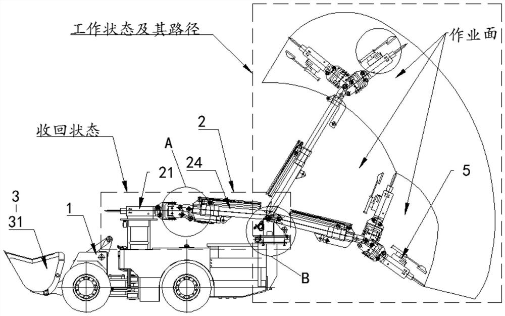
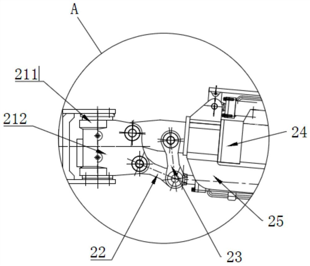
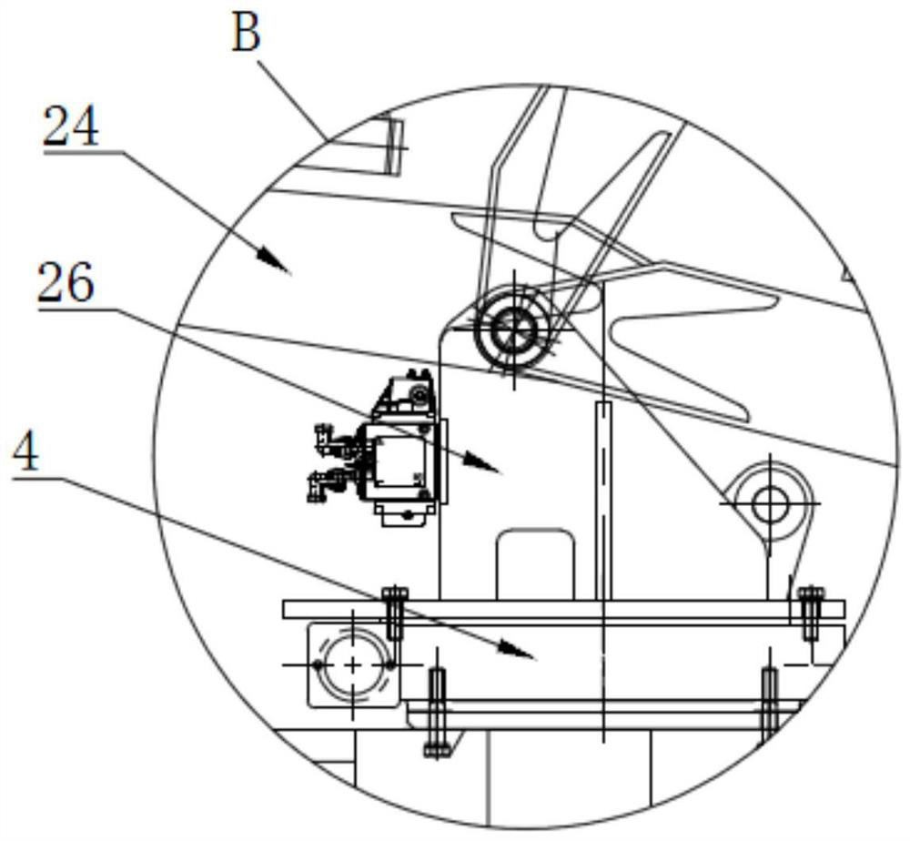
[0040] A prying scraper for underground mining, such as figure 1 and Figure 4 Shown, comprise car body 1 and be arranged on car body 1 pry hair mechanism 2 and scraper mechanism 3, wherein, scraper mechanism 3 is arranged on the front side of car body 1, pry hair mechanism 2 is arranged on car body 1 The rear side is driven by the hydraulic rotary mechanism 4 to rotate; when the prying scraper is walking, the hydraulic rotary mechanism 4 drives the prying mechanism 2 to rotate to the front of the car body 1; when working, the hydraulic rotary mechanism 4 drives the prying Hair mechanism 2 rotates to car body 1 rear side and pries hair.

[0041] In order to improve the utilization rate of the equipment, the present invention is provided with a prying mechanism 2 and a shoveling mechanism 3 on the car body 1, and the mine is pried by the prying mechanism 2, and then the ore is transported out by the shoveling mechanism 3 In order to improve the operating area of ​​the prying ...

Embodiment 2

[0050] Embodiment 2, the difference with embodiment 1 is

[0051] Such as figure 1 , 5 As shown, it also includes a tracking survey mechanism 5 for remote observation of prying effects; the tracking survey mechanism 5 includes a camera 51, a light fill device 52, a display screen, a remote gateway, a controller and a local dust suction structure 53; The camera 51 is installed on the prying mechanism 2 through a lifting structure and is electrically connected to the controller and the display screen through a remote gateway; the light supplement 52 is installed directly below the camera 51 and is electrically connected to the controller; the dust suction structure 53 includes being arranged directly above the camera 51 through the telescopic component 8.

[0052] The dust collection structure includes a vacuum cleaner, a collection bucket, and a flexible pipe with a telescopic function; the vacuum cleaner is installed on the output end of the telescopic part and moves with th...

Embodiment 3

[0061] In addition, the present invention also discloses a prying and shoveling method for an underground mining prying and shoveling machine, which is characterized in that it includes the following steps:

[0062] S1 Pre-survey: Pre-survey the position of the prying hair through the survey mechanism, and have realized the proofreading and positioning of the output position of the prying hair mechanism;

[0063] S2 prying: when working, the hydraulic rotary mechanism drives the prying mechanism to rotate to the rear side of the car body for prying;

[0064] S3 Survey: While the prying work is in progress, the survey mechanism starts, the vacuum mechanism moves to the prying area through the telescopic mechanism to absorb the dust generated by the prying, the light fill device starts to illuminate the prying area, and the camera clearly captures the prying area The condition of the rock wall; the prying mechanism can be adjusted freely according to the actual rock wall conditi...


PUM


Abstract

The invention belongs to the technical field of mining equipment, and particularly relates to an underground mining stone-prying carry-scraper. The carry-scraper comprises a vehicle body, a stone-prying mechanism and a carry-scraper mechanism, the stone-prying mechanism and the carry-scraper mechanism are arranged on the vehicle body, the carry-scraper mechanism is arranged on the front side of the vehicle body, and the stone-prying mechanism is arranged on the rear side of the vehicle body and driven by a hydraulic rotating mechanism to rotate. In order to increase the operation area of the stone-prying mechanism, namely, the stone-prying mechanism can excavate a mine in a larger range under the condition that the vehicle body is not moved, the carry-scraper mechanism is arranged on the front side of the vehicle body, the stone-prying mechanism is arranged on the rear side of the vehicle body, the stone-prying mechanism is driven to rotate through the hydraulic rotating mechanism, in the advancing process of the vehicle body, the stone-prying mechanism is rotated to the front of the vehicle body through the hydraulic rotating mechanism, during stone prying operation, the stone-prying mechanism is rotated to the rear of the vehicle body through the hydraulic rotating mechanism, and then the purpose of widening the stone prying operation range is achieved.

Description

technical field [0001] The invention belongs to the technical field of mining equipment, and in particular relates to an underground mining prying scraper and a mining method thereof. Background technique [0002] Underground stopes of small and medium-sized mines generally have small scale and small operating space. Therefore, manual prying is generally used in the stope prying operation. However, the safety risk of manual prying is relatively large. In order to reduce the risk of mining operations, underground Mechanized rock drilling and mining equipment such as rock drilling jumbo, prying jumbo and scraper have been added to the mine. However, the addition of the above equipment will result in higher investment costs, and there are problems such as difficulty in equipment transfer due to space constraints in the stope. , resulting in low equipment utilization. [0003] Publication No. is the Chinese invention patent of CN209723079U, which discloses a prying, digging and...

Claims


Application Information

Patent Timeline
Patent Type & Authority Applications(China)
IPC IPC(8): E02F3/96E02F9/20E02F9/22E21C27/20E21C31/10E21C35/20
CPCE02F3/961E02F9/2037E02F9/2264E21C27/20E21C31/10E21C35/20
Inventor 王守宁
Owner 浙江兰溪市金昌矿业有限公司
Why Eureka
Try Eureka