Heat exchange tube fin with corrugations

A technology of heat exchange tubes and fins, which is applied in the field of heat exchange and heating equipment, can solve the problems of easy formation of fouling and large volume of heat exchangers, and achieve the effects of reducing difficulty, reducing volume and increasing rigidity

Active Publication Date: 2021-05-14
XI AN JIAOTONG UNIV
View PDF5 Cites 0 Cited by
  • Summary
  • Abstract
  • Description
  • Claims
  • Application Information

AI Technical Summary

Problems solved by technology

[0003] At present, the H-shaped fins and annular fins used more often will cause air separation and backflow in the leeward area during heat exchange. It is difficult for dust particles to flow between different fins, so it is easy to form ash accumulation. In order to reduce the impact of ash accumulation on heat transfer The impact of the finning ratio is usually lower, so the heat exchanger has a larger volume

Method used


Image

  • Heat exchange tube fin with corrugations
  • Heat exchange tube fin with corrugations
  • Heat exchange tube fin with corrugations

Examples


Embodiment Construction

[0023] The present invention will be described in further detail below in conjunction with the accompanying drawings and specific embodiments, so that the advantages and features of the present invention can be more easily understood by those skilled in the art, so as to define the protection scope of the present invention more clearly.

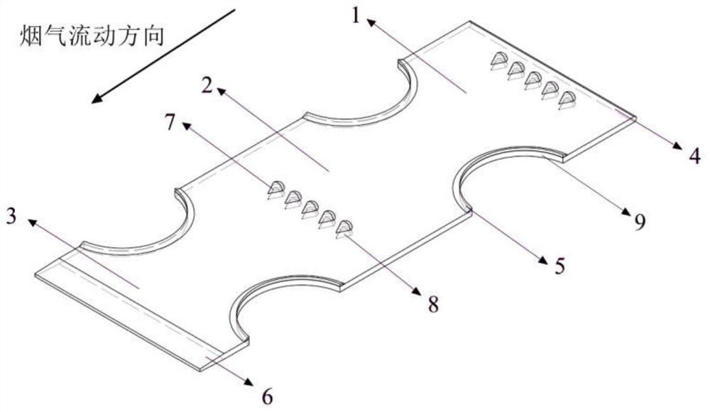
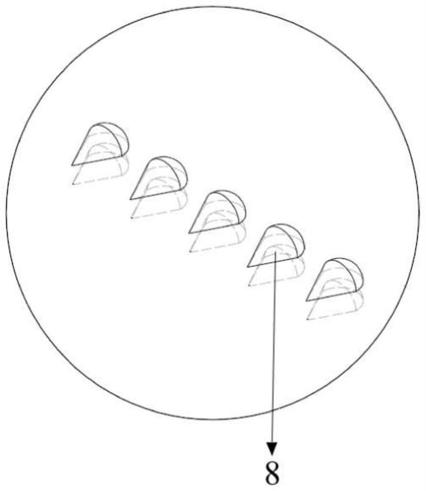
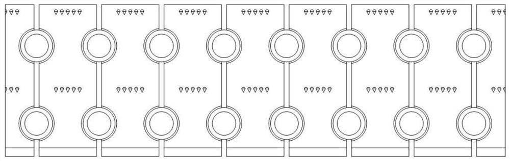
[0024] Such as figure 1 As shown, a corrugated heat exchange tube fin includes a windward area 1, a heat exchange enhanced area 2, a leeward area 3, an arc-shaped windward surface 4, an extended chamfer 5, the end of the leeward area 6, corrugations 7 and concave Groove 9; the fins are symmetrically and uniformly provided with a plurality of grooves 9 along both sides of the flue gas flow direction, along the flue gas flow direction, from the point where the flue gas enters the fin to the beginning of the first groove 9 The part is the windward area 1, the heat transfer enhancement area 2 starts from the first groove 9 passing through the dir...


PUM


Abstract

The invention discloses a heat exchange tube fin with corrugations. Two sides of the fin are provided with grooves and extended chamfers, and the fin is divided into a windward area, an enhanced heat exchange area and a leeward area by the grooves along a flue gas flowing direction; the windward area and the enhanced heat exchange area are provided with a large number of streamline-structured corrugations; and the leeward area is fins with gradually-changed thickness. The structure is good in heat exchange performance, small in flowing resistance and good in flue gas waste heat recovery effect, the airflow separation and backflow phenomena occurring in the leeward area can be effectively improved, the fin temperature field and flue gas speed collaboration is enhanced, the heat exchange efficiency is improved, meanwhile, dust accumulation is effectively reduced, and flowing channel blockage is avoided.

Description

technical field [0001] The invention relates to a heat exchange tube fin, in particular to a corrugated heat exchange tube fin used in waste heat recovery, which is suitable for various types of heat exchange in industries such as petroleum, chemical industry, metallurgy, electric power, and energy. and heating equipment. Background technique [0002] Energy is an important basis for human economic and social progress. With the continuous growth of energy consumption in my country, energy conservation and emission reduction has become a long-term policy for my country's economic and social development. Thermal power plants account for the largest proportion in the power industry, and it is very urgent to improve the energy utilization efficiency of thermal power units. Coal-fired power plants are usually equipped with economizers to recover the waste heat of flue gas to achieve the purpose of energy saving. It is a common way to increase the heat transfer area of ​​the hea...

Claims


Application Information

Patent Timeline
Patent Type & Authority Applications(China)
IPC IPC(8): F28F1/12
CPCF28F1/128
Inventor 王进仕谢坤圆胡文帅聂嘉灼姚辰邢张梦严俊杰刘明刘继平
Owner XI AN JIAOTONG UNIV
Why Eureka
Try Eureka