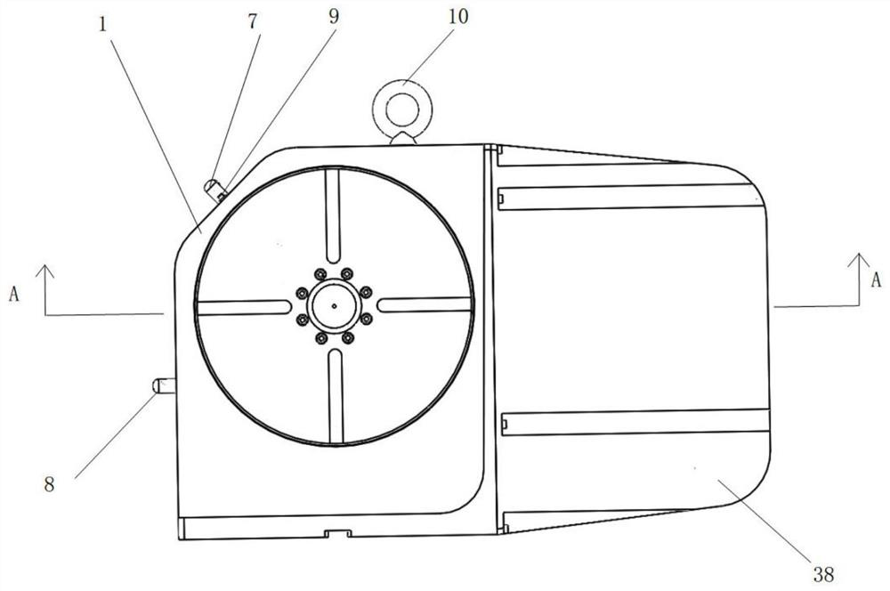
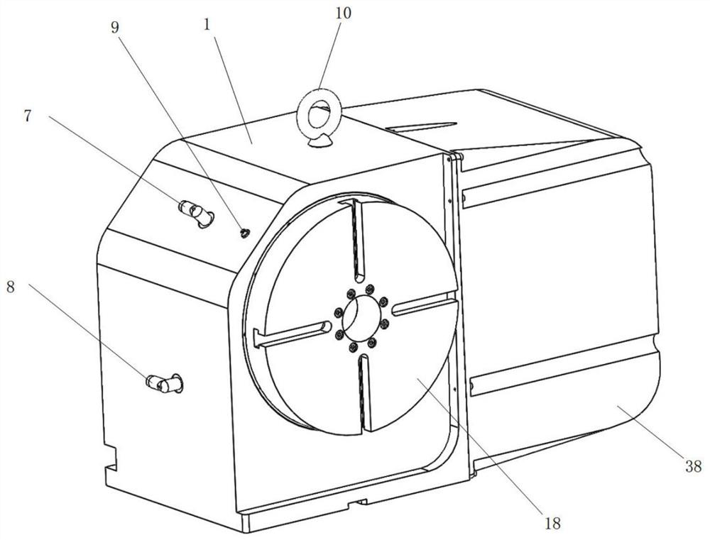
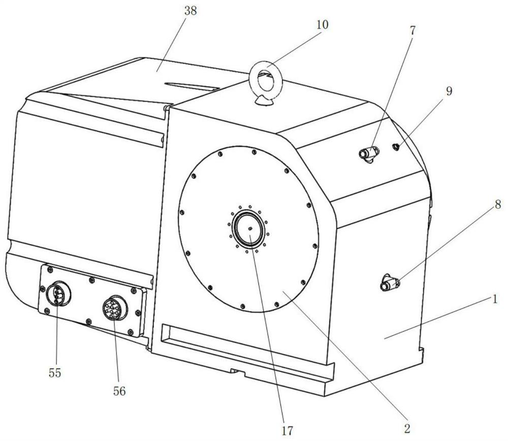
Modularized harmonic drive numerical control rotary table

A technology of harmonic transmission and numerical control turntable, which is applied in the direction of large fixed members, metal processing machinery parts, metal processing equipment, etc., and can solve problems such as high cost, reduced transmission accuracy, and transmission wear

Inactive Publication Date: 2021-05-18
江苏开璇智能科技有限公司
View PDF5 Cites 0 Cited by
  • Summary
  • Abstract
  • Description
  • Claims
  • Application Information

AI Technical Summary

Problems solved by technology

But for the worm gear and roller cam reduction transmission mechanism, due to its special structure, although the worm gear reduction transmission mechanism can achieve a large reduction ratio, its transmission efficiency is low, the transmission wear is serious, and the transmission accuracy decreases with the wear and tear of use. Significantly lower, regular maintenance is required, and special self-lubricating precious metals are required for worm manufacture
Although the roller cam reduction transmission mechanism has been improved on the basis of the worm gear, its essential principle is still based on the worm gear transmission, and because the processing of the cam is complicated and the cost is high, it is difficult to popularize it.
In summary, although the CNC turntable using worm gear and roller cam reduction transmission mechanism can realize its technical functions, it still has many shortcomings in terms of manufacturing, use and maintenance costs.

Method used


Image

  • Modularized harmonic drive numerical control rotary table
  • Modularized harmonic drive numerical control rotary table
  • Modularized harmonic drive numerical control rotary table

Examples


Embodiment Construction

[0030] The technical solutions of the present invention will be described in detail below through embodiments with reference to the accompanying drawings. It should be noted here that the descriptions of these embodiments are used to help understand the present invention, but are not intended to limit the present invention.

[0031] The term "and / or" in this article is just an association relationship describing associated objects, which means that there may be three relationships, for example, A and / or B, which can mean: A exists alone, B exists alone, and A and B exist simultaneously. In the three cases of B, the term " / and" in this article is to describe another associated object relationship, which means that there can be two relationships, for example, A / and B, which can mean: there is A alone, and there are two cases of A and B alone , In addition, the character " / " in this article generally indicates that the contextual objects are an "or" relationship.

[0032] accor...


PUM


Abstract

The invention discloses a modularized harmonic drive numerical control rotary table which comprises a harmonic speed reduction part, a power supply part, a hydraulic brake part, an auxiliary output part and a fixing shell. The harmonic speed reduction part, the power supply part, the hydraulic brake part and the auxiliary output part are all arranged on the fixing shell. The harmonic speed reduction part comprises a harmonic speed reducer, an input shaft, a transmission flange, an output shaft and an output disc, wherein the harmonic speed reduction part is arranged on the fixing shell, the input shaft and the transmission flange are both arranged on the harmonic speed reducer, and the output shaft is arranged on the transmission flange. The power supply part comprises a protective shell, a motor, a transmission part and a tensioning part, wherein the protective shell, the motor and the tensioning part are all arranged on the fixing shell. The transmission device is reasonable in structural design, simple in structure, high in transmission precision, large in bearing capacity and rigidity, long in service life, high in transmission efficiency, simple in manufacturing process, low in manufacturing cost, free of regular back clearance adjustment and suitable for being used in a large range.

Description

technical field [0001] The invention relates to the technical field of numerically controlled turntables, and more specifically, the invention relates to a modularized harmonic drive numerically controlled turntable. Background technique [0002] CNC turntable is an important machine tool accessory, which is mainly used in machining centers and CNC boring and milling machines to expand the processing capacity from 3 axes to 4 axes or 5 axes, so as to realize more complex and precise parts processing and manufacturing. At present, most CNC turntable manufacturers on the market use the following two types of turntable deceleration mechanisms: one is to use worm gear as the deceleration transmission mechanism, and the other is to use roller cam as the deceleration transmission mechanism; the power input end is controlled by the CNC machine tool. Due to the limitations of the operating system, generally use a branded motor that supports a specific CNC operating system. The advan...

Claims


Application Information

Patent Timeline
IPC IPC(8): B23Q1/25
CPCB23Q1/25Y02P70/10
Inventor 储建华鄢旋经方成杨丽君
Owner 江苏开璇智能科技有限公司
Why Eureka
Try Eureka