
High borosilicate glass kettle automatic nozzle leading system and control method thereof

A high borosilicate glass and glass pot technology, which is applied in glass manufacturing equipment, glass molding, glass remolding, etc. To achieve complete unity and other issues

Active Publication Date: 2021-05-18
KUNMING UNIV OF SCI & TECH
View PDF15 Cites 1 Cited by
  • Summary
  • Abstract
  • Description
  • Claims
  • Application Information

AI Technical Summary

Problems solved by technology

The method of forming and bonding the spout of the pot body separately will leave wrinkles, so at present, this process can only be done manually by workers. There will be differences in the position of the spout, the shape of the spout, and the angle of the spout of each pot, resulting in glass pots. poor quality
Moreover, due to the complete manual processing, the efficiency is low, and it is impossible to achieve complete uniformity between batches, and it is impossible to produce in large quantities.
[0003] The existing and pending related patents mainly focus on solving the problem of forming the high borosilicate glass pot of the cold water pot type with only a single top spout, but cannot solve the problem of forming the borosilicate glass pot spout of the teapot type with a spout on the side
For example, "An automated production system for high borosilicate glass pots (application number: 201711453513.8)" proposes a production system in which a blowing machine and a forming mold cooperate with each other, but it can only produce high-boron high-boron water pots with a single top spout Silicon glass pot
"A High Borosilicate Glass Spout Forming Device (Application No.: 201711455885.4)" proposes to realize the molding operation of the high borosilicate glass spout by means of a turntable and extrusion molding mechanism, but it is still only suitable for a single top spout high borosilicate glass pot

Method used


Image

  • High borosilicate glass kettle automatic nozzle leading system and control method thereof
  • High borosilicate glass kettle automatic nozzle leading system and control method thereof
  • High borosilicate glass kettle automatic nozzle leading system and control method thereof

Examples


Embodiment 1

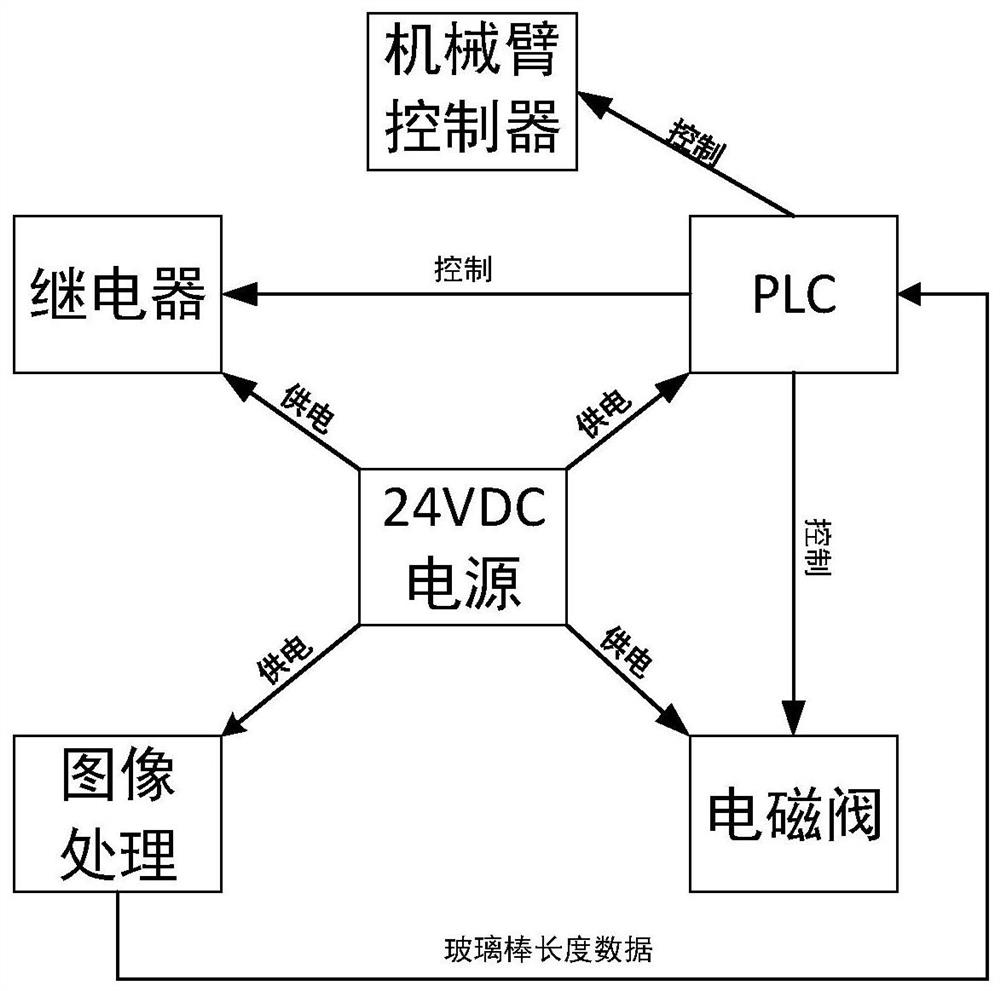
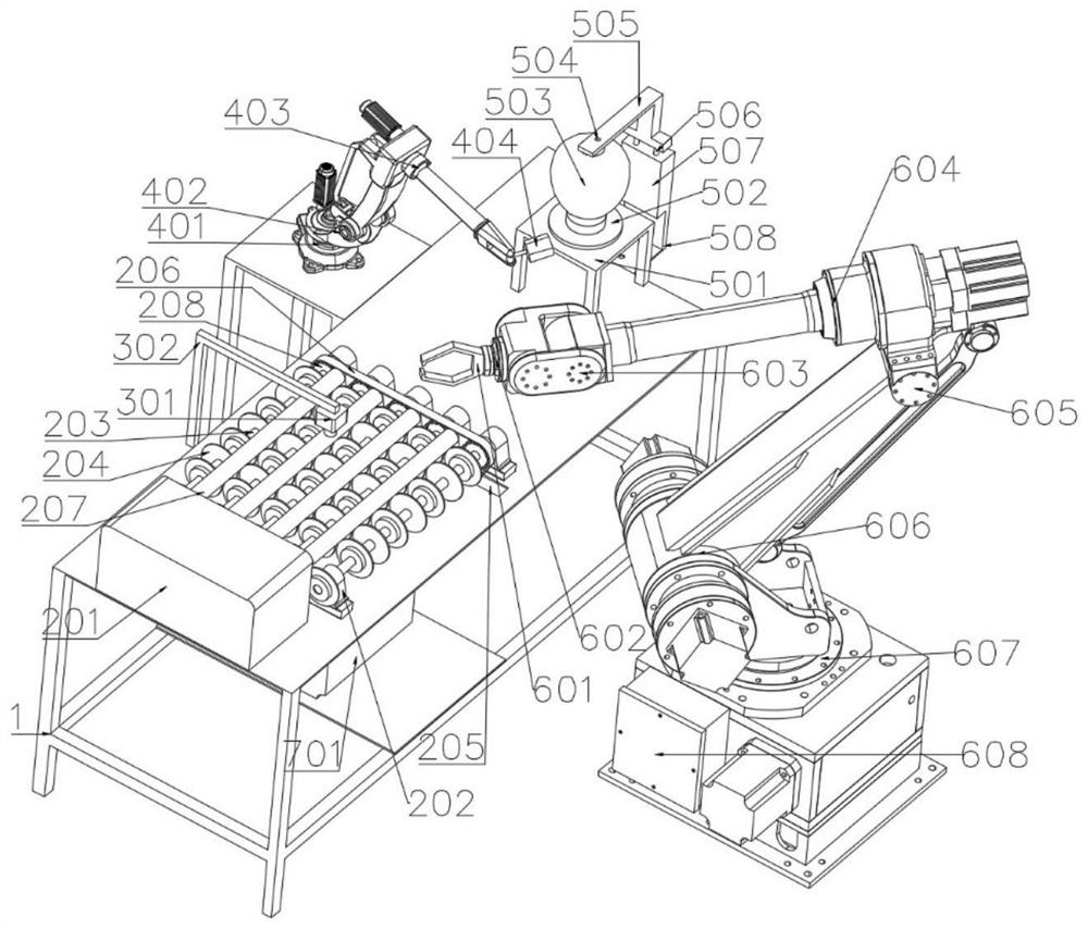
[0042] Example 1, see Figure 1-Figure 8 , a high borosilicate glass pot automatic nozzle system, including a workbench 1, a high borosilicate glass rod melting table 2, a vision system 3, a mobile fire nozzle mechanical arm 4, a high borosilicate glass pot blowing table 5, a high Borosilicate glass pot and glass rod clamping mechanical arm 6, control box 8;

[0043] The high borosilicate glass pot blowing table 5 includes a high borosilicate glass pot body support table 501, a gasket 502, and a kettle body pressurizing rod 505; the high borosilicate glass pot body support table 501 is installed at the end of the workbench 1, and Four pillars support a horizontal platform, the size of the platform is larger than the largest part of the pot body, the sealing gasket 502 is located at the center of the horizontal platform, and its diameter is larger than the mouth of the pot, the center of the horizontal platform and the sealing gasket 502 has an opening, and the lower part of th...


PUM


Abstract

The invention relates to a high borosilicate glass kettle automatic nozzle leading system and a control method thereof, and the system comprises a high borosilicate glass rod melting table, a high borosilicate glass kettle blowing table, a visual system, a high borosilicate glass kettle and glass rod clamping mechanical arm, a movable fire-jet head mechanical arm, and a control box. The high borosilicate glass rod melting table comprises a constant-temperature electric heating furnace and a high borosilicate glass rod rotating bracket composed of a rotating shaft, a material supporting wheel and a gear motor, the high borosilicate glass kettle blowing table comprises a supporting table top, a sealing gasket and a kettle body pressurizing rod, and the visual system can recognize the real-time length of a glass rod. The system is high in automation degree and high in production efficiency, and uniform quality of products in different batches is ensured.

Description

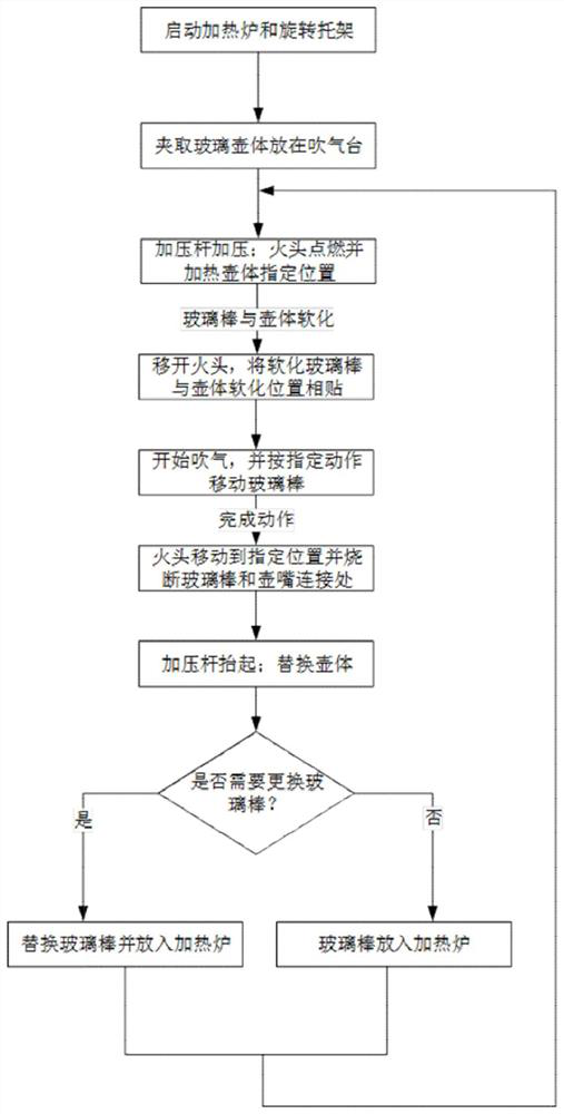
technical field [0001] The invention relates to an automatic spout system for a high borosilicate glass jug and a control method thereof, belonging to the field of glassware mechanical equipment. Background technique [0002] The spout on the side of the high borosilicate glass pot is generally heated by heating the spout of the glass pot, and then sticking the molten part of the heated glass rod at one end to the spout after heating, blowing air into the glass pot at the same time, and following the The shape of the mouth pulls the glass rod, and after the nozzle action of the glass pot is completed, the joint between the glass rod and the spout is melted with a flame, and the glass rod is separated from the spout. The method of forming and bonding the spout of the pot body separately will leave wrinkles, so at present, this process can only be done manually by workers. There will be differences in the position of the spout, the shape of the spout, and the angle of the spou...

Claims


Application Information

Patent Timeline
IPC IPC(8): C03B23/09
CPCC03B23/091
Inventor 王剑平程天相
Owner KUNMING UNIV OF SCI & TECH
Learn More