Reinforced concrete pipe jacking pipe joint and machining die thereof

A reinforced concrete and mold processing technology, which is applied in the direction of manufacturing tools, sewer pipeline systems, waterway systems, etc., can solve the problems of affecting the service life of pipe jacking, unfavorable pipe jacking construction, and hindering pipe joint jacking construction, etc.

Active Publication Date: 2021-05-18
浙江银泰水泥构件股份有限公司
View PDF4 Cites 0 Cited by
  • Summary
  • Abstract
  • Description
  • Claims
  • Application Information

AI Technical Summary

Problems solved by technology

Pipe jacking construction has high requirements on the waterproof performance of pipe joints, but in many engineering projects, water leakage occurs in pipe joints
[0004] However, in the process of pipe jacking construction, there is inevitably frictional resistance between the outer surface of the pipe jacking and the soil, which will generate force on the surface of the pipe jacking, and for ordinary connected pipe jacking, it will cause shaking between the pipe jacking , which is not conducive to pipe jacking construction, and it is very easy to cause misalignment and movement at the joint joints of pipe jacking, resulting in damage to the lining at the joint of pipe jacking due to excessive force, and loss of sealing at the joint, resulting in pipeline leakage and affecting pipe jacking service life, and at the same time, after the dislocation of the connection of the pipe joint occurs, it will hinder the jacking construction of the pipe joint

Method used


Image

  • Reinforced concrete pipe jacking pipe joint and machining die thereof
  • Reinforced concrete pipe jacking pipe joint and machining die thereof
  • Reinforced concrete pipe jacking pipe joint and machining die thereof

Examples


Embodiment 1

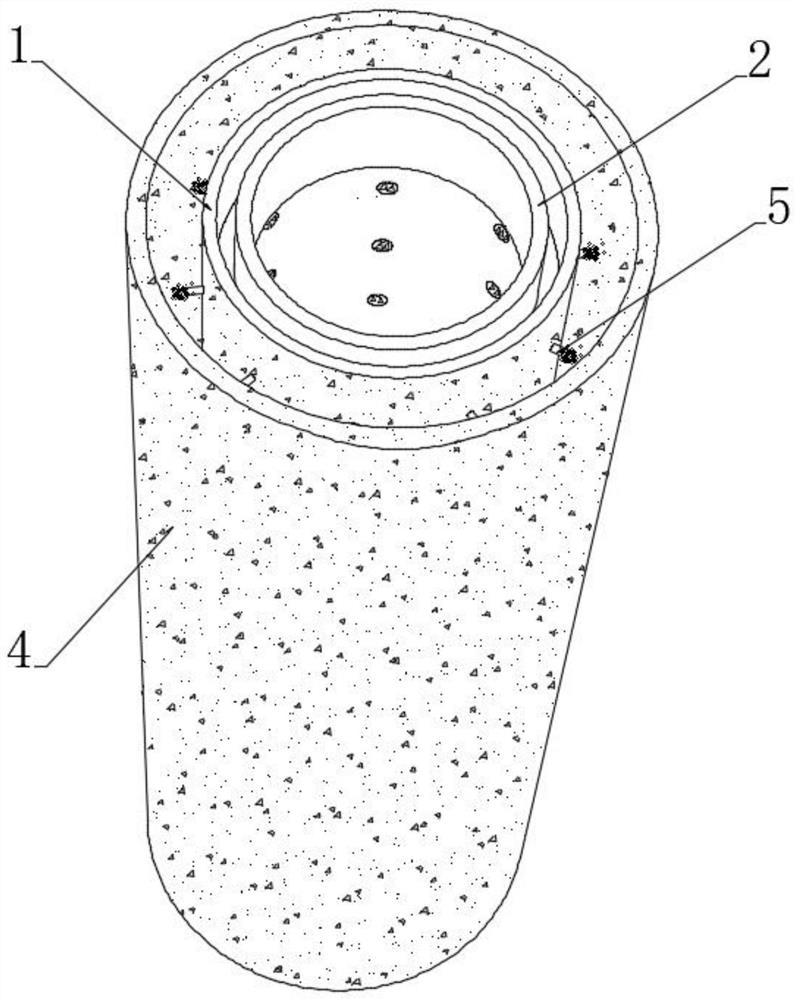
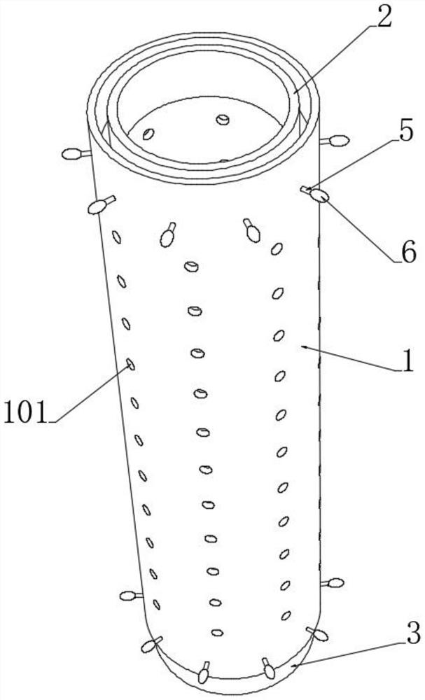
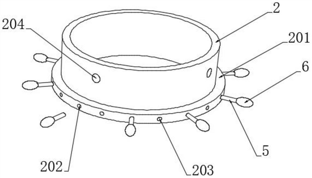
[0043] see Figure 1-5 , the reinforced concrete pipe jacking pipe joint, including the thin inner steel bar 1, the upper and lower ends of the inner steel bar thin tube 1 are respectively fixedly connected with the outer connecting tube 2 and the inner supporting tube 3, and the inner supporting tube 3 is exposed at one end of the outer side of the inner reinforcing bar thin tube 1 It is the inner connection part, and the outer side of the outer connection pipe 2 is provided with an outer bearing cavity 201 for matching the inner connection part. When the pipe joints are butted, the inner connecting part on the inner bearing pipe 3 is fastened to the outer bearing cavity 201 of the outer connecting pipe 2. The end walls are connected and embedded to realize the sealing of the connection of the pipe joints. The outer connection pipe 2, the inner support pipe 3 and the inner wall of the thin inner steel tube 1 are connected. One end is the upper joint part and the lower joint p...


PUM


Abstract

The invention discloses a reinforced concrete pipe jacking pipe joint and a machining die thereof, and belongs to the technical field of reinforced concrete pipe jacking pipe joints. An outer connecting pipe and an inner bearing pipe which are matched with each other are arranged at the upper end and the lower end of an inner thin steel bar pipe, and transverse reinforcing bodies which are annularly distributed are arranged at the joints of the outer connecting pipe, the inner bearing pipe and the inner thin steel bar pipe, so that the connecting strength of the contact positions of every two adjacent transverse reinforcing bodies is improved; after concrete filler is poured, the outer side of the inner thin steel bar pipe is filled with the concrete filler, and the concrete filler is bonded with the transverse reinforcing bodies, so that the overall mechanical strength of the inner thin steel bar pipe, the outer connecting pipe, the inner bearing pipe and a concrete forming layer is further improved; meanwhile, a plurality of elastic buckling bag heads are annularly distributed on the inner connecting part, and the elastic buckling bag heads are matched with buckling grooves in a one-to-one mode, so that the bearing connection of the inner bearing pipe and the outer connecting pipe is realized when the two pipe joints are connected; and through multi-point buckling connection, the strength is enhanced, and the situation that the connecting position of the pipe jacking pipe joint is subjected to friction due to jacking construction operation, so that dislocation movement occurs, and the sealing performance is reduced is not prone to being caused.

Description

technical field [0001] The invention relates to the technical field of reinforced concrete pipe-jacking pipe joints, and more specifically relates to a reinforced concrete pipe-jacking pipe joint and a processing mold thereof. Background technique [0002] Reinforced concrete pipe jacking is a kind of sewage pipe that is made of cement, steel bars, sand, stones, etc. as raw materials and mixed with a centrifuge. It is mainly used for drainage tasks such as urban rainwater, sewage, or farmland irrigation and drainage. It is a municipal construction project. non-excavation submerged pipe jacking technology. [0003] In recent years, with the rapid promotion and application of non-excavation technology, especially pipe jacking technology, pipe jacking technology has been widely used in the field of municipal engineering, in which electric pipe jacking is used for the underground laying of cables, and large-diameter reinforced concrete pipes are used as the Mainly, the interfac...

Claims


Application Information

Patent Timeline
Patent Type & Authority Applications(China)
IPC IPC(8): E03F3/04E03F3/06B28B19/00B28B7/00
CPCE03F3/04E03F3/06B28B19/0038B28B7/00
Inventor 钱建新
Owner 浙江银泰水泥构件股份有限公司
Why Eureka
Try Eureka