Novel insulating flange

A flange, a new type of technology, applied in the direction of flange connections, pipes/pipe joints/fittings, passing components, etc., can solve the problems of high processing precision requirements, troublesome installation and processing, and large space occupation of sealing waterlines

Pending Publication Date: 2021-05-18
厦门市卓励石化设备有限公司 +1
View PDF0 Cites 0 Cited by
  • Summary
  • Abstract
  • Description
  • Claims
  • Application Information

AI Technical Summary

Problems solved by technology

[0005] 1. The processing accuracy of the sealing water line is high, and an insulating gasket needs to be added. The correspondence between the two flanges is relatively high, and it needs to be practical with the insulating joint, and the installation and processing are more troublesome.
[0006] 2. Insulated flanges and insulated joints are used together, which takes up a lot of space and the overall quality is heavy
[0007] 3. In order to meet the strength requirements, the traditional insulation flange insulation joints are often made of metal materials, and the inner wall has high roughness, and the medium is easy to remain on the metal surface to cause deterioration and corrosion
[0008] 4. The indispensable parts of traditional insulating flanges and insulating joints are steel pipes with a thickness of 2-8mm, which are difficult to apply in low-temperature environments. If they are replaced with insulating plastic materials, the strength of pipes with a thickness of 2-8mm is far less than to request

Method used


Image

  • Novel insulating flange
  • Novel insulating flange
  • Novel insulating flange

Examples


Embodiment 1

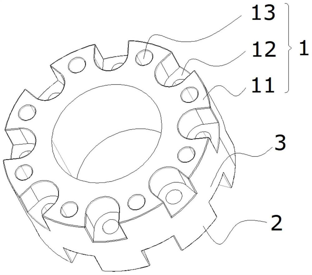
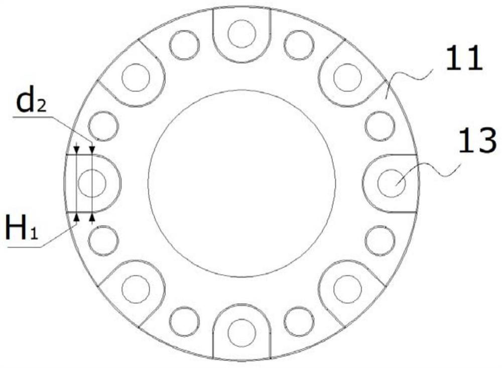
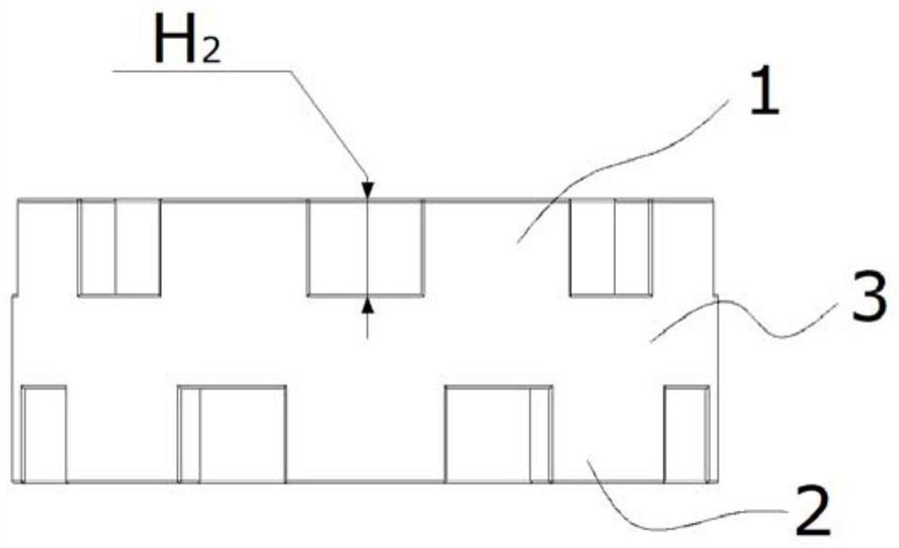
[0040] A new type of insulating flange, which is detachably arranged on the joint of the pipeline, is characterized in that it includes an integrally formed flange, and the flange includes an upper flange 1, a lower flange 2 and a The connecting portion 3 between the upper flange 1 and the lower flange 2; wherein, the upper flange 1 includes a plurality of installation parts 11 and slots 12 arranged at intervals, on the installation part 11 A threaded through hole 13 that runs through the upper flange 1 and the connecting portion 3 is provided; the lower flange 2 has the same structure as the upper flange 1; the upper flange 1 and the The lower flanges 2 are staggered, wherein, the installation part 11 of the upper flange 1 corresponds to the slot 12 of the lower flange 2, and the slot 12 of the upper flange 1 corresponds to the lower flange 1. The mounting part 11 of the flange 2 corresponds.

[0041] By integrally forming the upper flange 1 and the lower flange 2, and inter...

Embodiment 2

[0050] On the basis of Embodiment 1, this embodiment also provides an insulating flange that can be installed without a wrench. As a further improvement, the slot 12 passes through the thread from the flange mounting surface. The hole 13 is machined axially, and the bottom plane of the slot 12 is parallel to the mounting surface of the flange.

[0051] In order to ensure the bolt connection strength, preset nuts or preset threaded sleeves are set in the slot 12. The shape of the slot 12 includes but is not limited to rectangle, circle, regular hexagon or special shape. The shape of the slot 12 Adapt to the preset nut or preset threaded sleeve.

[0052] As a further improvement, if a preset nut is set in the slot 12, the thickness of the preset nut is defined as h 2 , the depth of the groove 12 is H 3 , then there is H 3 = 2h 2 ; If the preset threaded sleeve is embedded in the slot 12, the axial length of the preset threaded sleeve is defined as h 3 , then there is H 3 =...


PUM

PropertyMeasurementUnit
thicknessaaaaaaaaaa
thicknessaaaaaaaaaa
thicknessaaaaaaaaaa

Abstract

A novel insulating flange is detachably arranged on a connector of a pipeline and comprises an integrally-formed flange plate, and the flange plate comprises an upper flange plate body, a lower flange plate body and a connecting part arranged between the upper flange plate body and the lower flange plate body. The upper flange plate body comprises a plurality of mounting parts arranged at intervals and open grooves, and threaded through holes penetrating through the upper flange plate body and the connecting part are formed in the mounting parts. The lower flange plate body and the upper flange plate body are the same in structure. The upper flange plate body and the lower flange plate body are arranged in a staggered mode, the mounting parts of the upper flange plate body correspond to the open grooves of the lower flange plate body, and the open grooves of the upper flange plate body correspond to the mounting parts of the lower flange plate body. The flange plate is made of low-temperature-resistant insulating plastic, and the low-temperature-resistant insulating plastic is one or a composite material of UPE (Unplasticized Polyethylene) or PTFE (Polytetrafluoroethylene).

Description

technical field [0001] The invention relates to the field of pipeline transportation equipment, in particular to a novel insulating flange. Background technique [0002] Insulating flanges are products produced for petroleum, chemical and other industries. They are mainly used between gas transmission and distribution pipelines, gas pressure regulation, metering, storage and other equipment. They are also used in petrochemical, food and wharf industries. The sections of the transmission and distribution pipeline, equipment and pipelines are insulated from each other to protect them from chemical corrosion. [0003] Traditional insulating flanges are usually composed of a pair of flanges, and a sealing water line is processed between the flanges. One method is to install flange insulating gaskets between two butt welding flat flanges and install insulating sleeves and insulating bolt gaskets on the fastening bolts; the other method is to use steel flat flanges Instead of th...

Claims


Application Information

Patent Timeline
Patent Type & Authority Applications(China)
IPC IPC(8): F16L23/032F16L23/036
CPCF16L23/032F16L23/036
Inventor 陈国英
Owner 厦门市卓励石化设备有限公司
Why Eureka
Try Eureka