Curing oven and tubular column conveying and rotating device and method used in curing oven

A technology of rotating device and curing furnace, which is applied in the direction of the device, furnace and furnace material for coating liquid on the surface, which can solve the problems of easy falling off, thin coating thickness and affecting large-scale application

Active Publication Date: 2021-05-18
CHINA PETROLEUM & CHEM CORP +1
View PDF9 Cites 1 Cited by
  • Summary
  • Abstract
  • Description
  • Claims
  • Application Information

AI Technical Summary

Problems solved by technology

However, due to the low adhesion of the coating, it is easy to fall off; the thickness of the coating is thin, and the coating is easily damaged due to the wear and tear of the rod and tube, which affects its large-scale application.

Method used


Image

  • Curing oven and tubular column conveying and rotating device and method used in curing oven
  • Curing oven and tubular column conveying and rotating device and method used in curing oven
  • Curing oven and tubular column conveying and rotating device and method used in curing oven

Examples


Embodiment 1

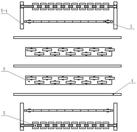
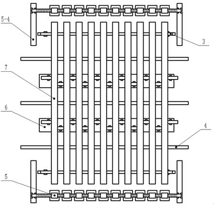
[0079] see Figure 1 to Figure 6 , the present invention provides a technical solution: a curing furnace, comprising:

[0080] An outer casing 1, a heating rod 2 is arranged inside the outer casing;

[0081] Also includes:

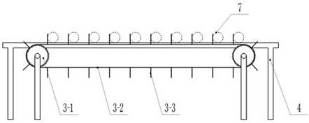
[0082] The pipe string conveying rotating device, the pipe string conveying rotating device is arranged inside the outer casing; the pipe string conveying rotating device includes a pipe feeding device 3, an auxiliary supporting lifting device 6, and a clamping rotating device 5, and the auxiliary supporting lifting device It is located on the inner side of the tube delivery device, and the tube delivery device is located on the inner side of the clamping and rotating device.

[0083] Further, there are two tube delivery devices, which are the front tube delivery device and the rear tube delivery device, and are arranged symmetrically to each other;

[0084] Two auxiliary support lifting devices are provided, which are respectively a front auxiliary sup...

Embodiment 2

[0114] see Figure 1 to Figure 6 , the present invention provides a technical solution: a curing furnace, comprising:

[0115] An outer casing 1, a heating rod 2 is arranged inside the outer casing;

[0116] Also includes:

[0117] The pipe string conveying rotating device, the pipe string conveying rotating device is arranged inside the outer casing; the pipe string conveying rotating device includes a pipe feeding device 3, an auxiliary supporting lifting device 6, and a clamping rotating device 5, and the auxiliary supporting lifting device It is located on the inner side of the tube delivery device, and the tube delivery device is located on the inner side of the clamping and rotating device.

[0118] Further, there are two tube delivery devices, which are the front tube delivery device and the rear tube delivery device, and are arranged symmetrically to each other;

[0119] Two auxiliary support lifting devices are provided, which are respectively a front auxiliary sup...

Embodiment 3

[0141] see Figure 1 to Figure 6 , the present invention provides a technical solution: a curing furnace, comprising:

[0142] An outer casing 1, a heating rod 2 is arranged inside the outer casing;

[0143] Also includes:

[0144] The pipe string conveying rotating device, the pipe string conveying rotating device is arranged inside the outer casing; the pipe string conveying rotating device includes a pipe feeding device 3, an auxiliary supporting lifting device 6, and a clamping rotating device 5, and the auxiliary supporting lifting device It is located on the inner side of the tube delivery device, and the tube delivery device is located on the inner side of the clamping and rotating device.

[0145] Further, there are two tube delivery devices, which are the front tube delivery device and the rear tube delivery device, and are arranged symmetrically to each other;

[0146] Two auxiliary support lifting devices are provided, which are respectively a front auxiliary sup...


PUM


Abstract

The invention discloses a curing oven and a tubular column conveying and rotating device and method used in the curing oven. The curing oven comprises: an outer shell, wherein a heating rod is arranged in the outer shell; the tubular column conveying and rotating device, wherein the tubular column conveying and rotating device is arranged in the outer shell. The tubular column conveying and rotating device comprises a tube conveying device, an auxiliary supporting and lifting device and a clamping and rotating device, wherein the auxiliary supporting and lifting device is located on the inner side of the tube conveying device, and the tube conveying device is located on the inner side of the clamping and rotating device. According to the curing oven, the functions of automatic conveying, clamping, rotating and curing of an oil tube can be achieved, the oil tube obtained after solvent-free liquid spraying is kept in the rotating state in the curing process, it is guaranteed that a sprayed coating is free of sagging and cured evenly, and the spraying quality of the internally-coated oil tube is guaranteed.

Description

technical field [0001] The invention relates to the technical field of curing of internal oil-coated pipes, in particular to a curing furnace and a pipe string conveying rotating device and method used inside the curing furnace. Background technique [0002] During the oilfield production process, the tubing is prone to corrosion, wear, fatigue and breakage due to the immersion of the high-salinity output fluid, the contact with the sucker rod during pumping, and the alternating load of the pumping inertia. At present, the internally coated tubing used in the oil field mainly uses epoxy powder as a coating to spray on the inner wall of the tubing, and forms an internal coating after curing. However, due to the low adhesion of the coating, it is easy to fall off; the thickness of the coating is thin, and the coating is easily damaged due to the wear and tear of the rod tube, etc., which have affected its large-scale application. In order to overcome the above problems, solve...

Claims


Application Information

Patent Timeline
IPC IPC(8): F27D3/12B05D3/02
CPCF27D3/12B05D3/0272F27M2003/08
Inventor 张雷智勤功张中慧唐倩雯付增郝丽伟苏秋涵刘常福闫文文
Owner CHINA PETROLEUM & CHEM CORP
Why Eureka
Try Eureka